( TF09EABK72100000000BBAT10 )
How to Troubleshoot the Fuel and Emissions Systems

Intermittent Failures
The term ‘‘intermittent failure'' means a system may have had a failure, but it checks OK now. If the malfunction indicator lamp (MIL) on the dash does not come on, check for poor connections or loose terminals at all connectors related to the circuit that you are troubleshooting. If the MIL was on but then went out, the original problem may have been intermittent.

Service Information
Periodically, new ECM/PCM software or new service procedures may become available. Always check online for the latest software or service information related to the DTCs or symptoms you are troubleshooting.

Opens and Shorts
‘‘Open'' and ‘‘short'' are common electrical terms. An open is a break in a wire or at a connection. A short is an accidental connection of a wire to ground or to another wire. In simple electronics, this usually means something won't work at all. With complex electronics (such as ECMs or PCMs) this can sometimes mean something works, but not the way it's supposed to.

How to Use the HDS (Honda Diagnostic System)

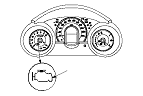
If the MIL (malfunction indicator lamp) has come on

  1. Start the engine, and check the MIL (A).

  1. If the MIL stays on, connect the HDS to the data link connector (DLC) (A) located under the driver's side of the dashboard.
  1. Turn the ignition switch to ON (II).
  1. Make sure the HDS communicates with the ECM/PCM and other vehicle systems. If it doesn't, go to the DLC circuit troubleshooting.
  1. Check the diagnostic trouble code (DTC) and note it. Also check the freeze data and/or on-board snapshot data, and download any data found. Then refer to the indicated DTC's troubleshooting, and begin the appropriate troubleshooting procedure.
    NOTE:
    • Freeze data indicates the engine conditions when the first system malfunction, misfire, or fuel trim malfunction that activated the MIL was detected.
    • The HDS can read the DTC, freeze data, on-board snapshot, current data, and other engine control module (ECM) or powertrain control module (PCM) data.
    • For specific operations, refer to the user's manual that came with the HDS.


If the MIL did not stay on

If the MIL did not stay on but there is a driveability problem, do the symptom troubleshooting.


If you can't duplicate the DTC

Some of the troubleshooting requires you to reset the ECM/PCM and try to duplicate the DTC. If the problem is intermittent and you can't duplicate the code, do not continue through the procedure. To do so will only result in confusion and possibly, a needlessly replaced ECM/PCM.

HDS Clear Command
The ECM/PCM stores various specific data to correct the system even if there is no electrical power such as when the battery negative terminal is disconnected. Stored data based on failed parts should be cleared by using the ‘‘CLEAR COMMAND'' of the HDS, if parts are replaced.
The HDS has three kinds of clear commands to meet this purpose. They are clear DTCs, ECM/PCM reset, and CKP pattern clear. DTC clear command erases all stored DTC codes, freeze data, and on-board snapshot. This must be done with the HDS after reproducing the DTC during troubleshooting.
The ECM/PCM reset command erases all stored DTC codes, freeze data, on-board snapshot, and all specific data to correct the system except CKP pattern. If the CKP pattern data in the ECM/PCM was cleared, you must do the CKP pattern learn procedure. The CKP pattern clear command erases only CKP pattern data. This command is for repair of a misfire or the CKP sensor.

Scan Tool Clear Command
If you are using a generic scan tool to clear commands, be aware that there is only one setting for clearing the ECM/PCM, and it clears all commands at the same time (CKP pattern learn, idle learn, freeze data, on-board snapshot, and DTCs). After you clear all commands, you then need to do these procedures, in this order: ECM/PCM idle learn procedure; CKP pattern learn procedure.

DTC Clear
  1. Clear the DTC with the HDS while the engine is stopped.
  1. Turn the ignition switch to LOCK (0).
  1. Turn the ignition switch to ON (II), and wait 30 seconds.
  1. Turn the ignition switch to LOCK (0), and disconnect the HDS from the DLC.

ECM/PCM Reset
  1. Reset the ECM/PCM with the HDS while the engine is stopped.
  1. Turn the ignition switch to LOCK (0).
  1. Turn the ignition switch to ON (II), and wait 30 seconds.
  1. Turn the ignition switch to LOCK (0), and disconnect the HDS from the DLC.

CKP Pattern Clear/CKP Pattern Learn
Clear/Learn Procedure (with the HDS)
  1. Connect the HDS to the data link connector (DLC) (A) located under the driver's side of the dashboard.
  1. Turn the ignition switch to ON (II).
  1. Make sure the HDS communicates with the ECM/PCM and other vehicle systems. If it doesn't, go to the DLC circuit troubleshooting.
  1. Select CRANK PATTERN in the ADJUSTMENT MENU with the HDS.
  1. Select CRANK PATTERN LEARNING with the HDS, and follow the screen prompts.
  1. The CKP pattern learn procedure is complete.
Learn Procedure (without the HDS)
  1. Start the engine. Hold the engine speed at 3,000 rpm (min −1 ) without load (A/T in P or N, M/T in neutral) until the radiator fan comes on.
  1. Test-drive the vehicle on a level road: Decelerate (with the throttle fully closed) from an engine speed of 2,500 rpm (min −1 ) down to 1,000 rpm (min −1 ) with the A/T in 2 position, or the M/T in 1st gear.
  1. Repeat Step 2 several times.
  1. Turn the ignition switch to LOCK (0).
  1. Turn the ignition switch to ON (II), and wait 30 seconds. The CKP pattern learn procedure is complete.

How to End a Troubleshooting Session (required after any troubleshooting)
  1. Reset the ECM/PCM with the HDS.
  1. Turn the ignition switch to LOCK (0).
  1. Disconnect the HDS from the DLC.
    NOTE: The ECM/PCM is part of the immobilizer system. If you replace the ECM/PCM, it will have a different immobilizer code. In order for the engine to start, you must rewrite the immobilizer code with the HDS (immobilizer system section).

How to Troubleshoot Circuits at the ECM/PCM Connectors
NOTE: The ECM/PCM stays on up to about 15 minutes after the ignition switch is turned to LOCK (0). Jumping the SCS line after turning the ignition switch to LOCK (0) cancels this function. Disconnecting the ECM/PCM during this function, without jumping the SCS line first, can damage the ECM/PCM.
  1. Jump the SCS line with the HDS.
  1. Disconnect ECM/PCM connectors A, B, and C.
    NOTE: ECM/PCM connectors A, B, and C have symbols (A=□, B=△, C=○) embossed on them for identification.

  1. When diagnosis/troubleshooting is done at the ECM/PCM connector, use the terminal test port (A) above the terminal you need to check.

  1. Connect one side of the patch cord (A) terminals to a commercially available digital multimeter (B), and connect the other side of the patch cord terminals to a commercially available banana jack (Pomona Electronics Tool No. 3563 or equivalent) (C).
  1. Gently contact the pin probe (male) at test port from the terminal side. Do not force the tips into the terminals.
    • For accurate results, always use the pin probe (male).
    • To prevent damage to the connector terminals, do not insert test equipment probes, paper clips, or other substitutes as they can damage the terminals. Damaged terminals cause a poor connection and an incorrect measurement.
    • Do not puncture the insulation on a wire. Punctures can cause poor or intermittent electrical connections.

Substituting the ECM/PCM
Special Tools Required
  • Honda diagnostic system (HDS)
  • Honda interface module (HIM)
  • HDS pocket tester
NOTE: Use this procedure when you have to substitute a known-good ECM/PCM during troubleshooting procedure.
  1. Connect the HDS to the data link connector (DLC) (A) located under the driver's side of the dashboard.
  1. Turn the ignition switch to ON (II).
  1. Make sure the HDS communicates with the ECM/PCM and other vehicle systems. If it doesn't, go to the DLC circuit troubleshooting.
  1. Select the READ DATA in the REPLACE ECM/PCM MENU with the HDS.
    NOTE: If the READ DATA fails, ask the customer about the fuel grade (alcohol contained level) in the fuel tank (main), and go to Step 5 .
  1. Jump the SCS line with the HDS.
  1. Turn the ignition switch to LOCK (0).

  1. Remove the ECM/PCM cover (A).

  1. Remove the battery setting plate, and reposition the battery (D) away from the ECM/PCM.
    NOTE: Do not disconnect the battery terminals.
  1. Remove the bolts (E).
  1. Disconnect ECM/PCM connectors A, B, and C, then remove the ECM/PCM (F).
    NOTE: ECM/PCM connectors A, B, and C have symbols (A=□, B=△, C=○) embossed on them for identification.
  1. Install a known-good ECM/PCM in the reverse order of removal.
  1. Turn the ignition switch to ON (II).
    NOTE: DTC P0630 ‘‘VIN Not Programmed or Mismatch'' may be stored because the VIN has not been programmed into the ECM/PCM; ignore it, and continue this procedure.
  1. Manually input the VIN to the ECM/PCM with the HDS.
  1. Select the IMMOBI SYSTEM with the HDS.
  1. Enter the immobilizer code using the ECM/PCM replacement procedure in the HDS; it allows you to start the engine.
  1. Reset the ECM/PCM with the HDS.
  1. Update the ECM/PCM if it does not have the latest software.
  1. Start the engine.
    • If the engine starts, go to Step 30 .
    • If the engine does not start, go to Step 19 .
  1. Select MAIN FUEL TANK ALCOHOL CONTENT in the ADJUSTMENT MENU with the HDS.
  1. Select the appropriate ALCOHOL CONTENT in the HDS screen by the customer's information on Step 4 .
    NOTE: If the customer did not remember about it, go to Step 21 .
  1. Try to start the engine.
    • If the engine starts, go to Step 30 .
    • If the engine does not start, go to Step 22 .
  1. Select LOW ALCOHOL CONTENT and try to start the engine.
    • If the engine starts, go to Step 30 .
    • If the engine does not start, go to Step 23 .
  1. Select 50 % ALCOHOL CONTENT and try to start the engine.
    • If the engine starts, go to Step 30 .
    • If the engine does not start, go to Step 24 .
  1. Select 90 % ALCOHOL CONTENT and try to start the engine.
    • If the engine starts, go to Step 30 .
    • If the engine does not start, go to Step 25 .
  1. Select 100 % ALCOHOL CONTENT and try to start the engine.
    • If the engine starts, go to Step 30 .
    • If the engine does not start, go to Step 26 .
  1. Fill the fuel tank (main) with a gasoline.
  1. Select LOW ALCOHOL CONTENT and try to start the engine.
  1. Do the CKP pattern learn procedure.

OBD Status
The OBD status shows the current system status of each DTC and all of the parameters. This function is used to see if the repair was successfully completed. The results of diagnostic tests for the DTC are displayed as:
  • PASSED: The on board diagnosis is successfully finished.
  • FAILED: The on board diagnosis has finished but failed.
  • EXECUTING: The vehicle is in enable criteria conditions for the DTC and the on board diagnosis is running.
  • NOT COMPLETED: The on board diagnosis was running but is out for the enable conditions for the DTC.
  • OUT OF CONDITION: The vehicle has stayed out of the enable conditions for the DTC.