( TF09E8YB20200000000MBAT00 )
Wheel Alignment

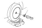
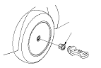
Special Tool Required

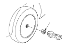
Wheel alignment gauge attachment, 56 x 62 mm
07NAJ-SS00301
The suspension can be adjusted for front camber and front toe. However, each of these adjustments are interrelated to each other. For example, when you adjust the camber, the toe will change. Therefore, you must adjust the front wheel alignment whenever you adjust camber or toe.
Pre-Alignment Checks
For proper inspection and adjustment of the wheel alignment, do these checks:
  1. Release the parking brake to avoid an incorrect measurement.
  1. Make sure the suspension is not modified.
  1. Make sure the fuel tank is full, and that the spare tyre or the temporary repair kit, the jack, and the tools are in place on the vehicle.
  1. Check the tyre size and tyre pressure according to tyre information.
  1. Check the suspension ball joints.
  1. Before doing alignment inspections, be sure to remove all extra weight from the vehicle, and no one should be inside the vehicle (driver or passengers).
  1. Bounce the vehicle up and down several times to stabilize the suspension.
  1. Check that the steering column is set at the center tilt and telescopic position.

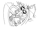
Front Caster Inspection
  1. Raise the front of the vehicle, and remove the wheel caps.
    NOTE: Push out the cap on the aluminum wheel from the inside after removing the wheel.
  1. Set the turning radius gauges beneath the front wheels, and place the boards under the rear wheels the same thickness as the turning radius gauges, then lower the vehicle.
    NOTE: Be sure that the vehicle is level with the wheels on the turning radius gauges and the boards.
  1. Install the wheel alignment gauge attachment (A) and camber/caster gauge on the wheel hub, and apply the front brake.
  1. Turn the front wheel 20 ° outward, then turn the adjusting screw of the camber/caster gauge to set the bubble at 0 °.
  1. Turn the wheel 20 ° inward and read the caster angle on the gauge with the bubble at the center of the gauge.
    Front caster angle:
    3 ° 13 '± 1 °

    • If the measurement is within specifications, measure the front camber angle.
    • If the measurement is not within specifications, check for bent or damaged suspension components.

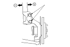
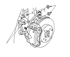
Front Camber Inspection
  1. Turn the front wheels to the straight ahead position.
  1. Raise the front of the vehicle, and remove the wheel caps.
    NOTE: Push out the cap on the aluminum wheel from the inside after removing the wheel.
  1. Install the wheel alignment gauge attachment (A) and camber/caster gauge on the wheel hub.
  1. Read the camber angle on the gauge with the bubble at the center of the gauge.
    Front camber angle:
    0 ° 07 '± 1 °
    (Maximum difference between the right and left side: 0 ° 45 ')

    • If the measurement is within specifications, measure the rear camber.
    • If the measurement for the front camber is not within specifications, go to the front camber adjustment.

Front Camber Adjustment
The front camber can be adjusted by exchanging one or both of the damper pinch bolts with the smaller diameter adjusting bolt(s). The difference between the adjusting bolt diameter and the pinch bolt hole diameter allows for a small range of adjustment.

  1. Remove the front wheels.
  1. Loosen the damper pinch bolts (A), and adjust the camber angle by moving the bottom of the damper within the range of the damper pinch bolt free play.
  1. Tighten the damper pinch bolts to the specified torque.
  1. Clean the mating surfaces of the brake disc and the inside of the wheel, then install the front wheels.
  1. Lower the vehicle to the ground, and bounce the front of the vehicle up and down several times to settle the suspension.
  1. Measure the camber angle.
    • If the measurement is within specification, measure the rear camber.
    • If the measurement is not within specification, go to Step 8 .
  1. Remove the front wheels.

  1. Replace the damper pinch bolts with the adjusting bolts (A), and adjust the camber angle.
    NOTE:
    • The camber angle can be adjusted up to ±20 ' (center of tolerance) by replacing one damper pinch bolt with the adjusting bolt.
    • The camber angle can be adjusted up to ±40 ' by replacing both the damper pinch bolts with the adjusting bolts.
  1. Tighten the adjusting bolts to the specified torque value.
  1. Clean the mating surfaces of the brake disc and the inside of the wheel, then install the front wheels.
  1. Lower the vehicle to the ground, and bounce the front of the vehicle up and down several times to settle the suspension.
  1. Measure the camber angle. If the camber angle is not within specification, repeat Step 8 through 13 to readjust the camber angle. If the camber measurement is correct, measure the toe-in, and adjust it if necessary.

Rear Camber Inspection
  1. Raise the rear of the vehicle, and remove the wheel caps.
    NOTE: Push out the cap on the aluminum wheel from the inside after removing the wheel.
  1. Install the wheel alignment gauge attachment (A) and camber/caster gauge on the wheel hub.
  1. Read the camber angle on the gauge with the bubble at the center of the gauge.
    Rear camber angle:
    −1 ° 00 '±1 °
    (Maximum difference between the right and left side: 0 ° 45 ')

    • If the measurement is within specifications, measure the toe-in.
    • If the measurement is not within specifications, check for bent or damaged suspension components.

Front Toe Inspection/Adjustment
  1. Set the steering column to the middle tilt and telescopic positions. Center the steering wheel spokes, and hold it.
  1. Check the toe with the wheels pointed straight ahead.
    Front toe-in:
    0±3 mm (0±0.12 in.)

    • If adjustment is required, go to Step 3 .
    • If no adjustment is required, go to rear toe inspection.
  1. Loosen the tie-rod locknuts (A) while holding the flat surface sections (B) of the tie-rod end with a wrench, and turn both tie-rods (C) until the front toe is within specifications.
  1. After adjusting, tighten the tie-rod locknuts to the specified torque value. Reposition the rack end boot if it is twisted or displaced.
  1. Go to rear toe inspection.
    NOTE: Adjust both the right and left wheels at the same time by the same amount in opposite directions to obtain the correct toe and to keep the steering wheel straight.

Rear Toe Inspection
  1. Release the parking brake to avoid and incorrect measurement.
  1. Check the toe.
    Rear toe-in:
    2.5±2.5 mm (0.10±0.10 in.)

    • If the measurement is within specifications, measure the turning angle.
    • If the measurement is not within specifications, check for bent or damaged suspension components.

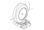
Turning Angle Inspection
  1. Raise the vehicle and set the turning radius gauges beneath the front wheels, and place the boards under the rear wheels the same thickness as the turning radius gauges, then lower the vehicle.
    NOTE: Be sure that the vehicle is level with the wheels on the turning radius gauges and the boards.
  1. Turn the wheel right and left while applying the brake, and measure the turning angle of the both wheels.
    Turning angle:
    Inward:
    40 ° 38 '±2 °
    Outward (reference):
    33 ° 30 '±1 °

  1. If the measurement is not within the specifications, even up both sides of the tie-rod threaded section length while adjusting the front toe. If it is correct, but the turning angle is not within the specifications, check for bent or damaged suspension components.