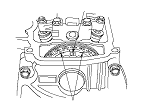
Cylinder Head Valve Clearance Adjustment
|
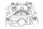
L15A7 engine
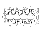
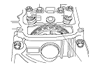
L13Z1 engine
|
|
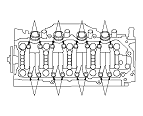
L15A7 engine
L13Z1 engine
|
|
|
|
|
|
|
|
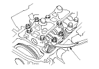
L15A7 engine
L13Z1 engine
|
|
L15A7 engine
L13Z1 engine
|
|
|
|
|
|
|