( TF09E8VD14300014781LDAT00 )
Brake Master Cylinder Reassembly

NOTE:
  • Clean all parts in brake fluid and air dry; blow out all passages with compressed air.
  • Before reassembling, check that all the parts are free of dirt and other foreign particles.
  • Replace parts with new ones whenever specified to do so.
  • Use only genuine DOT 3 or DOT 4 Honda Brake Fluid. Non-Honda brake fluid can cause corrosion and shorten the life of the system.
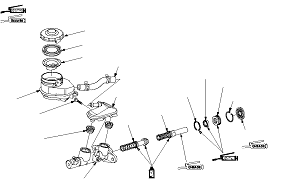
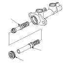
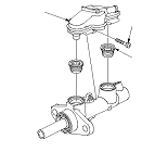
  • Replace the master cylinder if the bore is damaged or worn. Do not hone or attempt to refinish the bore.
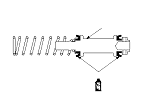
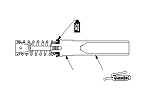
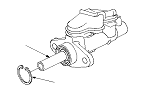
  • Coat the piston cups, pressure cup and master cylinder bore with clean brake fluid.
  • Use recommended greases in the master cylinder seal set.
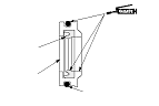
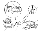
  • When you apply the silicone grease, make sure not to adhere to the terminal part of connectors and surrounding switches. Also do not touch the switches and the terminal part of connector by hands or glove that adheres the silicone grease.
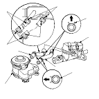
  • The illustrations show RHD model.
  1. Install the reservoir seal in the groove of the reservoir cap.
  1. Install the strainer, assembled reservoir cap on the reservoir tank.

  1. Coat the cups (A) of a new primary piston (B) with clean brake fluid, then install the primary piston into the master cylinder.

  1. Coat the cup (A) of a new secondary piston (B) with clean brake fluid, and apply the silicone grease to the piston surface (C).

  1. Apply the rubber grease to the piston guide (A), a new O-ring (B) and a new secondary cup (C).

  1. Install the primary piston (A), secondary piston (B) and piston guide (C) into the master cylinder. Make sure the direction of piston guide.

  1. Install the new grommets (A) and subreservoir (B) to the master cylinder.

  1. Install the new circlip (A) while pushing in the secondary piston (B). Be careful not to scratched damage on the piston surface with the circlip edges.

  1. Install the reservoir tank (A) and the reservoir tank hose (B) to the subreservoir (C).
    NOTE:
    • Align the ‘‘△'' mark (D) on the reservoir and subreservoir with the paint mark (E) on the hose.
    • Position the direction of the clamp (F).
RHD model
LHD model