|
HVAC Control (Lever type)
NOTE:
-
Do not use this troubleshooting procedure if any of these items are working properly with the A/C switch ON; condenser fan, radiator fan, A/C compressor, or if the heater does not work. Refer to the symptom troubleshooting index.
-
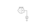
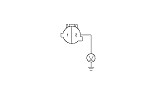
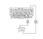
Check the A/C high-side pressure.
-
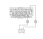
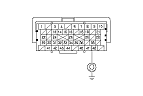
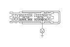
Disconnect the A/C pressure switch 2P connector.
-
Turn the ignition switch to ON (II).
-
Measure the voltage between the A/C pressure switch 2P connector No. 2 terminal and body ground.
|
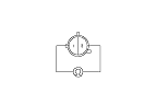
Is there battery voltage?
|
-
Turn the ignition switch to LOCK (0).
|