|
With HID
NOTE: Before testing, make sure that there is no DTC and combination light switch circuit is ok.
-
-
Turn the ignition switch to LOCK (0).
-
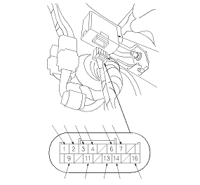
Disconnect the 16P connector (A) from the headlight auto leveling control unit (B).
-
Inspect the connector and socket terminals to be sure they are all making good contact.
-
With the connector still disconnected, make these input tests at the connector.
|
Cavity
|
Wire
|
Test condition
|
Test: Desired result
|
Possible cause if desired result is not obtained
|
|
9
|
BLK
|
Under all conditions
|
Check for continuity to ground: There should be continuity.
|
-
Poor ground (G301)
-
An open in the wire
|
|
1
|
LT GRN
|
Ignition switch ON (II)
|
Measure the voltage to ground: There should be battery voltage.
|
|
-
Reconnect the connector, turn the ignition switch to ON (II), and make these input tests at the connector.
-
If any tests indicates a problem, find and correct the cause, then recheck the system.
-
If all the input tests prove OK, replace the headlight leveling control unit.
|
Cavity
|
Wire
|
Test condition
|
Test: Desired result
|
Possible cause if desired result is not obtained
|
|
3
|
BRN
|
Under all conditions
|
Measure the voltage to ground: There should be less than 0.5 V.
|
-
Poor ground (G301)
-
An open in the wire
|
|
4
|
ORN
|
Under all conditions
|
Measure the voltage to ground: There should be less than 0.5 V.
|
-
Poor ground (G301)
-
An open in the wire
|
|
2
|
PUR
|
Ignition switch ON (II), headlight switch ON
|
Measure the voltage between the No. 2 and No. 3 terminals: There should be battery voltage.
|
|
|
3
|
BRN
|
|
11
|
LT BLU
|
Ignition switch ON (II), headlight switch ON
|
Measure the voltage between the No. 11 and No. 3 terminals: There should be about 2 to 12 V.
|
|
|
3
|
BRN
|
|
4
|
ORN
|
Ignition switch ON (II)
|
|
|
|
6
|
WHT
|
|
13
|
RED
|
|
4
|
ORN
|
Ignition switch ON (II)
|
|
|
|
7
|
PUR
|
|
13
|
RED
|
|