( TF09E8AA18316617502KBAT00 )
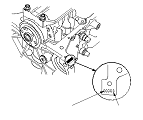
Crankshaft Main Bearing Replacement

Main Bearing Clearance Inspection
  1. Clean each main journal and bearing half with a clean shop towel.
  1. Place one strip of plastigage across each main journal.
  1. Reinstall the bearings and bearing cap bridge, then tighten the bearing cap bolts to 25 N·m (2.5 kgf·m, 18 lbf·ft) in the proper sequence.
    NOTE: Do not rotate the crankshaft during inspection.
  1. Tighten the bearing cap bolts an additional 40 °.

  1. Remove the bearing cap bridge and bearings again, and measure the widest part of the plastigage.

    Main Bearing-to-Journal Oil Clearance

    Standard (New):
    0.018−0.036 mm (0.0007−0.0014 in.)
    Service Limit:
    0.050 mm (0.0020 in.)

  1. If the plastigage measures too wide or too narrow, remove the crankshaft, and remove the upper half of the bearing. Install a new, complete bearing with the same color code(s), and recheck the clearance. Do not file, shim, or scrape the bearings or the caps to adjust clearance.
  1. If the plastigage shows the clearance is still incorrect, try the next larger or smaller bearing (the color listed above or below the current one), and check again. If the proper clearance cannot be obtained by using the appropriate larger or smaller bearings, replace the crankshaft and start over.

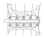
Main Bearing Selection
Crankshaft Bore Code Location
  1. Letters have been stamped on the end of the block as a code for the size of each of the five main journal bores. Write down the crank bore codes.
    If you can't read the codes because of accumulated dirt and dust, do not scrub them with a wire brush or scraper. Clean them only with solvent or detergent.

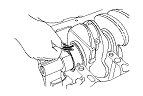
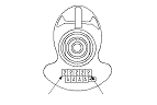
Main Journal Code Location
  1. The main journal codes are stamped on the crankshaft.

  1. Use the crank bore codes and crank journal codes to select the appropriate replacement bearings from the following table.
    NOTE: Color code is on the edge of the bearing.
L15A7 engine
L13Z1 engine
L12B1 engine