( TF09E8AA18316217201KBAT00 )
Connecting Rod Bearing Replacement

Rod Bearing Clearance Inspection
  1. Remove the connecting rod cap and bearing half.
  1. Clean the crankshaft rod journal and bearing half with a clean shop towel.
  1. Place plastigage across the rod journal.
  1. Reinstall the bearing half and cap, and torque the bolts to 9.8 N·m (1.0 kgf·m, 7.2 lbf·ft) +90 °.
    NOTE: Do not rotate the crankshaft during inspection.
  1. Remove the rod cap and bearing half, and measure the widest part of the plastigage.
    Connecting Rod Bearing-to-Journal Oil Clearance
    L15A7 engine:
    Standard (New):
    0.020−0.038 mm (0.0008−0.0015 in.)
    Service Limit:
    0.050 mm (0.0020 in.)
    L13Z1 engine:
    Standard (New):
    0.026−0.044 mm (0.0010−0.0017 in.)
    Service Limit:
    0.050 mm (0.0020 in.)
    L12B1 engine:
    Standard (New):
    0.026−0.044 mm (0.0010−0.0017 in.)
    Service Limit:
    0.050 mm (0.0020 in.)

  1. If the plastigage measures too wide or too narrow, remove the upper half of the bearing, install a new, complete bearing with the same color code(s), and recheck the clearance. Do not file, shim, or scrape the bearings or the caps to adjust clearance.
  1. If the plastigage shows the clearance is still incorrect, try the next larger or smaller bearing (the color listed above or below the current one), and check clearance again. If the proper clearance cannot be obtained by using the appropriate larger or smaller bearing, replace the crankshaft and start over.

Rod Bearing Selection
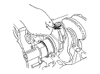
  1. Inspect each connecting rod for cracks and heat damage.
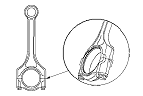
Connecting Rod Big End Bore Code Locations
  1. Each rod falls into one of four tolerance ranges (from 0 to 0.024 mm (0.0009 in.), in 0.006 mm (0.0002 in.) increments) depending on the size of its big end bore. It's then stamped with a number or bar (1, 2, 3, or 4) indicating the range. You may find any combination of 1, 2, 3, or 4 in any engine.
    If the codes are indecipherable because of an accumulation of dirt and dust, do not scrub them with a wire brush or scraper. Clean them only with solvent or detergent.
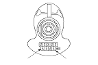
    Normal Bore Size:
    43.0 mm (1.69 in.)


Connecting Rod Journal Code Location
  1. The connecting rod journal codes are stamped on the crankshaft.

  1. Use the big end bore codes and rod journal codes to select appropriate replacement bearings from the following table.
    NOTE: Color code is on the edge of the bearing.
L15A7 engine
L13Z1 engine
L12B1 engine