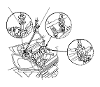
( TF09E8AA18223800000KCAT00 )
Engine Installation

Special Tools Required

Engine tilt hanger set
 07KAK-SJ40101

Engine hanger stay
 07KAK-SJ40200

Sub hanger stay
 07MAK-PY30100
  1. Raise the vehicle on the lift, and position the engine/transmission under the vehicle. Lower the vehicle, and attach the special tools to the engine/transmission, then lift the engine/transmission into position in the vehicle.
    NOTE: Reinstall the mounting bolts and support nuts in the sequence given in the following steps. Failure to follow this sequence may cause excessive noise and vibration, and reduce engine mount life.

  1. Install the side engine mount/bracket assembly (A), then tighten the new side engine mount/bracket assembly mounting bolts (B) and nuts (C).
  1. Loosely tighten the new side engine mount/bracket assembly mounting nuts.
  1. Install the ground cable (D).

  1. Install the transmission mount bracket (A), and loosely tighten the new transmission mount bracket mounting bolts and nuts (B).
  1. Install the ground cable (C).
  1. Remove the engine tilt hanger set from the engine/transmission
M/T model
A/T model
i-SHIFT model

  1. Remove the sub hanger stay.
  1. Raise the vehicle on the lift to full height.

  1. Install the front subframe, then tighten the new front subframe mounting bolts in the numbered sequence shown.

  1. Install the torque rod (A). Install the new bolt with the tab (B) on the bolt head aligned with the guide (C) on the front subframe, then loosely tighten the new torque rod mounting bolt and nut (D).
  1. Lower the vehicle on the lift.
M/T model
A/T model
i-SHIFT model

  1. Tighten the side engine mount/bracket assembly mounting nuts in the numbered sequence shown.

  1. Tighten the transmission mount mounting bolts and nuts in the numbered sequence shown.
  1. Raise the vehicle on the lift to full height.
M/T model
A/T model
i-SHIFT model

  1. Tighten the torque rod mounting bolt and nut in the numbered sequence shown.
M/T model
A/T model
i-SHIFT model

  1. Install the securing the steering gearbox and the steering gearbox stiffeners, then tighten the new bolts in the numbered sequence shown.
  1. Install a new set ring on the end of each driveshaft, then install the driveshafts. Make sure each ring ‘‘clicks'' into place in the differential and the intermediate shaft.

  1. Install the driveshaft heat shield.

  1. Install the A/C compressor (with A/C).

  1. Install the under-floor three way catalytic converter (under-floor TWC) (A). Use new gaskets (B) and new self locking nuts (C).

  1. Lower the vehicle on the lift.

  1. With RHD model: Install the brake fluid reservoir tank bracket mounting bolts.

  1. Install the heater hoses.

  1. Connect the secondary heated oxygen sensor (secondary HO2S) connector (A), then install the secondary HO2S harness to the clamps (B).

  1. Connect the fuel feed hose (A) , then install the quick-connect fitting cover (B) and the fuel feed hose clamp (C).

  1. Install the evaporative emission (EVAP) canister hose (A) and brake booster vacuum hose (B).

  1. Install the harness holder (A), then install the harness clamp (B).
  1. Connect the engine wire harness connector (C) and the engine control module (ECM)/powertrain control module (PCM) connectors (D).

  1. With M/T model: Install the battery base (A), then install the battery harness clamp (B).

  1. Without i-SHIFT model: Install the battery cables (A) to the battery terminal fuse box.
  1. Without i-SHIFT model: Install the harness clamps (B).

  1. With i-SHIFT model: Install the battery base (A) and harness clip (B).
  1. Install the front wheels.
  1. Refill the transmission with fluid:
  1. A/T model: Move the shift lever to each gear, and verify that the A/T gear position indicator follows the transmission range switch.
  1. M/T model: Check that the transmission shifts into all gear smoothly.
  1. Check the clutch operation.
  1. Inspect for fuel leaks. Turn the ignition switch to ON (II) (do not operate the starter) so the fuel pump runs for about 2 seconds and pressurizes the fuel line. Repeat this operation three times, then check for fuel leakage at any point in the fuel line.