( TF09E8AA14674300000KCAT00 )
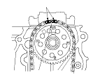
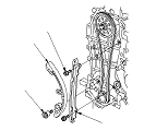
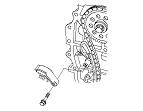
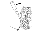
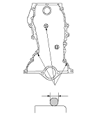
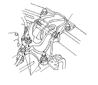
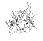
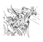
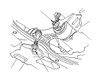
Cam Chain Installation

NOTE: Keep the cam chain away from magnetic fields.
  1. Set the crankshaft to top dead center (TDC). Align the TDC mark (A) on the crankshaft sprocket with the pointer (B) on the oil pump.
  1. Remove the crankshaft sprocket.

  1. Set the camshaft to TDC. The ‘‘UP'' mark (A) on the camshaft sprocket should be at the top, and the TDC grooves (B) on the camshaft sprocket should line up with the top edge of the head.

  1. Install the cam chain on the crankshaft sprocket with the colored piece (A) aligned with the TDC mark (B) on the crankshaft sprocket, then install the crankshaft sprocket to the crankshaft.

  1. With L15A7 engine: Install the cam chain on the camshaft sprocket with the pointers (A) aligned with the three colored pieces (B) as shown.

  1. With L13Z1 engine, L12B1 engine: Install the cam chain on the camshaft sprocket with the pointer (A) aligned with the center of the two colored pieces (B).

  1. Install the cam chain tensioner (A) and the cam chain guide (B).

  1. Install the cam chain tensioner slider, and tighten the bolt loosely.

  1. Apply new engine oil to the sliding surface of the cam chain tensioner slider (A).
  1. Rotate the cam chain tensioner slider clockwise to compress the cam chain tensioner, and install the remaining bolt, then tighten the bolts.
  1. Remove the all of the old liquid gasket from the chain case mating surfaces, the bolts, and the bolt holes.
  1. Clean and dry the chain case mating surfaces.

  1. Apply liquid gasket (P/N 08C70-K0234M, 08C70-K0334M, or 08C70-X0331S) to the engine block mating surface of the chain case and to the inner threads of the bolt holes.
    NOTE: Apply liquid gasket about 2.5 mm (0.098 in.) diameter bead along the broken line (A).

  1. Apply liquid gasket (P/N 08C70-K0234M, 08C70-K0334M, or 08C70-X0331S) to the oil pan mating surface of the chain case and to the inner threads of the bolt holes.
    NOTE:
    • Apply liquid gasket about 2.5 mm (0.098 in.) diameter bead along the broken line (A).
    • Apply liquid gasket about 5.0 mm (0.20 in.) diameter bead to the shaded area (B).
    • Do not install components if 5 minutes or more have passed after applying the liquid gasket. Instead, remove the old residue and reapply the liquid gasket.

  1. Set the edge of the chain case (A) to the edge of the oil pan (B), then install the chain case on the engine block (C).
    NOTE:
    • When installing the chain case, do not slide the bottom surface onto the oil pan mounting surface.
    • Wait at least 30 minutes before filling the engine with oil.
    • Do not run the engine for at least 3 hours after installing the chain case.

  1. Tighten the chain case mounting bolts. Wipe off the excess liquid gasket on the oil pan and the chain case mating area.
L15A7 engine
L13Z1 engine
L12B1 engine

  1. Install the side engine mount/bracket assembly (A), then tighten the new side engine mount/bracket assembly mounting bolts (B).
  1. Loosely tighten the new side engine mount/bracket assembly mounting nuts (C).
  1. Install the ground cable (D).

  1. Loosen the transmission mount bracket mounting bolts and nuts (A).
  1. Raise the vehicle on the lift to full height.
M/T model
A/T model
i-SHIFT model

  1. Loosen the torque rod mounting bolt and nut (A).
  1. Lower the vehicle on the lift.
M/T model
A/T model
i-SHIFT model

  1. Tighten the side engine mount/bracket assembly mounting nuts in the numbered sequence shown.

  1. Tighten the transmission mount mounting bolts and nuts in the numbered sequence shown.
  1. Raise the vehicle on the lift to full height.
M/T model
A/T model
i-SHIFT model

  1. Tighten the torque rod mounting bolt and nut in the numbered sequence shown.
  1. Lower the vehicle on the lift.
M/T model
A/T model
i-SHIFT model

  1. Install the A/C line bracket mounting bolt.

  1. Install the water pump pulley.
  1. Tighten the water pump pulley mounting bolts.
  1. Install the right side splash shield.
  1. Install the right front wheel.