( TF09E80J54200000000BBAT00 )
How to Troubleshoot the Body Electrical

Tips and Precautions

Before Troubleshooting

  1. Check applicable fuses in the appropriate fuse/relay box.
  1. Check the battery for damage, state of charge, and clean and tight connections.
    • Do not quick-charge a battery unless the battery ground cable has been disconnected, otherwise you will damage the alternator diodes.
    • Do not attempt to crank the engine with the battery ground cable loosely connected or you will severely damage the wiring.


Handling Connectors

  • Make sure the connectors are clean and have no loose wire terminals.
  • Make sure multiple cavity connectors are packed with dielectric grease (except watertight connectors).
  • All connectors have push-down release type locks (A).

  • Some connectors have a clip on their side used to attach them to a mount bracket on the body or on another component. This clip has a pull type lock.
  • Some mounted connectors cannot be disconnected unless you first release the lock and remove the connector from its mount bracket (A).

  • Never try to disconnect connectors by pulling on their wires; pull on the connector halves instead.
  • Always reinstall plastic covers.

  • Before connecting connectors, make sure the terminals (A) are in place and not bent.

  • Check for loose retainers (A) and rubber seals (B).

  • The backs of some connectors are packed with dielectric grease. Add grease if necessary. If the grease is contaminated, replace it.

  • Insert the connector all the way and make sure it is securely locked.
  • Position wires so that the open end of the cover faces down.


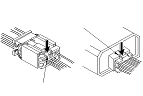
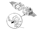
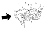
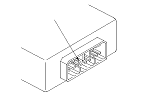
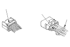
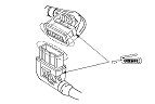
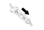
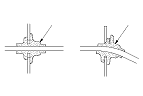
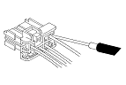
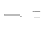
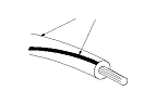
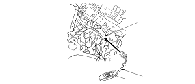
Handling Wires and Harnesses

  • Secure wires and wire harnesses to the frame with their respective wire ties at the designated locations.
  • Remove clips carefully; don't damage their locks (A).

  • After installing harness clips, make sure the harness doesn't interfere with any moving parts.
  • Keep wire harnesses away from exhaust components and other hot parts, from sharp edges of brackets and holes, and from exposed screws and bolts.
  • Seat grommets in their grooves properly (A). Do not leave grommets distorted (B).


Testing and Repairs

  • Do not use wires or harnesses with broken insulation. Replace them or repair them by wrapping the break with electrical tape.
  • Never attempt to modify, splice, or repair SRS wiring. If there is an open or damage is SRS wiring or terminals, replace the harness.
  • After installing parts, make sure that no wires are pinched under them.
  • When using electrical test equipment, follow the manufacturer's instructions and those described in this manual.
  • If possible, insert the probe of the tester from the wire side (except waterproof connector).

  • Use back probe adaptor 07TAZ-001020A.
  • Refer to the instructions in the Honda Terminal Kit for identification and replacement of connector terminals.

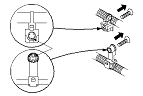
Five-step Troubleshooting
  1. Verify The Complaint:
    Turn on all the components in the problem circuit to verify the customer complaint. Note the symptoms. Do not begin disassembly or testing until you have narrowed down the problem area.
  1. Analyze The Schematic:
    Look up the schematic for the problem circuit. Determine how the circuit is supposed to work by tracing the current paths from the power feed through the circuit components to ground. If several circuits fail at the same time, the fuse or a ground is a likely cause.
    Based on the symptoms and your understanding of the circuit operation, identify one or more possible causes of the problem.
  1. Isolate The Problem By Testing The Circuit:
    Make circuit tests to check the diagnosis you made in Step 2 . Keep in mind that a logical, simple procedure is the key to efficient troubleshooting. Test for the most likely cause of failure first. Try to make tests at points that are easily accessible.
  1. Fix The Problem:
    Once the specific problem is identified, make the repair. Be sure to use proper tools and safe procedures.
  1. Make Sure The Circuit Works:
    Turn on all components in the repaired circuit in all modes to make sure you've fixed the entire problem. If the problem was a blown fuse, be sure to test all of the circuits on the fuse. Make sure no new problems turn up and the original problem does not recur.

Wire Color Codes
The following abbreviations are used to identify wire colors in the circuit schematics:
WHT. 
White
YEL. 
Yellow
BLK. 
Black
BLU. 
Blue
GRN. 
Green
RED. 
Red
ORN. 
Orange
PNK. 
Pink
BRN. 
Brown
GRY. 
Gray
PUR. 
Purple
LT BLU. 
Light Blue
LT GRN. 
Light Green

The wire insulation has one color or one color with another color stripe. The second color is the stripe.

Troubleshoot the B-CAN Circuit Related Problems
How to check for DTCs with the HDS (preferred method)
The HDS can check the F-CAN and B-CAN communication status, read and clear the DTCs, display the data list, and perform function test.
Check for DTCs
  1. Connect the HDS to the data link connector (A) located under the driver's side of the dashboard.
  1. Turn the ignition switch to ON (II).
  1. Make sure the HDS communicates with vehicle.
    NOTE: If the HDS does not communicate with the vehicle, troubleshoot the DLC circuit.
  1. Select the BODY ELECTRICAL, then select the desired TEST MODE menu, and check the DTCs. If the DTCs do not pertain to the select menu, select the All DTC Check icon to view all Body DTCs.
    NOTE: For specific operations, refer to the HDS user's manual.
  1. If any DTCs are indicated, go to the indicated DTCs troubleshooting.
    NOTE: If the DTC B1000, B1150, B1178, and/or B1900 are stored, troubleshoot these DTCs first (beginning with the lowest number).

How to check for DTCs without the HDS (Use only if the HDS is unavailable)
Special Tools Required

MPCS short connector
 07WAZ-0010100
If the HDS is unavailable, using the following method, you can check the B-CAN communication status, DTCs, and some F-CAN communication status related with the gauge control module.
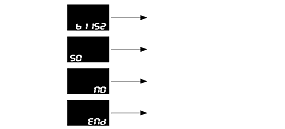
Check for DTCs

  1. Turn the ignition switch to ON (II).
  1. Connect the MPCS short connector (A) to the MICU service check connector (B), and turn the switch (C) ON.

  1. After 5 to 10 seconds, the DTCs which have been detected and stored individually by various B-CAN unit, will be indicated one by one on the odo/trip display if the communication line between the MICU and the gauge control module is OK. To scroll through the DTCs, press the select/reset button.
The unit that has stored the code can be identified by the number shown on the odo/trip display.
Control Unit
Control Unit I.D. Number
MICU
10
Gauge control module
50
Immobilizer-keyless control unit
96

NOTE: Also you can check the B-CAN communication status by following methods:

How to Clear the DTCs with the HDS
  1. Connect the HDS to the data link connector (A) located under the driver's side of the dashboard.
  1. Turn the ignition switch to ON (II).
  1. Clear the DTCs with the HDS.
  1. Turn the ignition switch to LOCK (0), and disconnect the HDS from the data link connector (DLC).

How to Clear the DTCs without the HDS
  1. While in DTCs indication status, press and hold the SELECT/RESET switch for more than 10 seconds.
  1. Turn the MPCS short connector switch off, and disconnect the connector from the MICU service check connector.
  1. Turn the ignition switch to LOCK (0).

HDS Inputs and Commands
Certain inputs happen so quickly that the HDS cannot update fast enough. Hold the switch that is being tested while monitoring the Data List. This should give the HDS time to update the signal on the Data List.
Because the HDS software is updated to support the release for newer vehicles it is not uncommon to see system function tests that are not supported.
Make sure that the most current software is loaded.

Input

System Menu
Data List
Data List Indication
Lighting
Driver's Door Switch
OFF/ON
Hazard Switch
OFF/ON
Headlight Switch (OFF)
OFF/ON
Headlight Switch (PARKING)
OFF/ON
Headlight Switch (HEADLIGHT)
OFF/ON
Headlight Switch (High Beam)
OFF/ON
Headlight Switch (PASSING)
OFF/ON
Turn Signal Switch (LEFT)
OFF/ON
Turn Signal Switch (RIGHT)
OFF/ON
Interior Light Command
OFF/ON
Left Turn Signal Command
OFF/ON
Right Turn Signal Command
OFF/ON
Cargo Light Command
OFF/ON
Headlight Command
OFF/ON
Headlight High Beam Command
OFF/ON
Parking Light Command
OFF/ON


HDS Inputs and Commands

Input

System Menu
Data List
Data List Indication
Gauges
Cruise Control Main Switch (ACC switch)
OFF/ON
Cruise Control Set Switch
OFF/ON
Cruise Control Resume Switch
OFF/ON
Engine Oil Pressure Switch
OFF/ON
Gauge Select/Reset Switch
OFF/ON
Parking Brake Switch
OFF/ON
Brake Fluid Level Switch
OFF/ON
Select/Reset Switch
OFF/ON
INFO Next Switch
OFF/ON
Fuel Sending Unit Input 2
v
ABS Indicator
OFF/ON
EBD Indicator (Electronic Brake Distribution)
OFF/ON
Cruise Control Main Switch Indicator
OFF/ON
MIL Indicator
OFF/ON
Low Oil Pressure Indicator
OFF/ON
Charging System Indicator
OFF/ON
Cruise Main Switch ON Indicator
OFF/ON
High Beam Indicator
OFF/ON
Parking Light ON Indicator
OFF/ON
Low Fuel Warning Indicator
OFF/ON
Security Indicator
OFF/ON
Seat Belt Indicator
OFF/ON
Door Open Indicator
OFF/ON
A/T Indicator
OFF/ON
SRS Indicator
OFF/ON
Side Airbag Cutoff Indicator
OFF/ON
Driver's Seat Belt Buckle Switch
OFF/ON
A/T Gear Position Switch (R)
OFF/ON
A/T Gear Position Switch (P)
OFF/ON


Input

System Menu
Data List
Data List Indication
Door Locks
Driver's Door Switch
OFF/ON
Front Passenger's Door Switch
OFF/ON
Driver's Rear Door Switch
OFF/ON
Passenger's Rear Door Switch
OFF/ON
Front Passenger's Door Lock Knob Switch (UNLOCK)
OFF/ON
Driver's Rear Door Lock Knob Switch (UNLOCK)
OFF/ON
Passenger's Rear Door Lock Knob Switch (UNLOCK)
OFF/ON
Driver's Door Key Cylinder Switch (LOCK)
OFF/ON
Driver's Door Key Cylinder Switch (UNLOCK)
OFF/ON
Driver's Door Lock Switch (LOCK)
OFF/ON
Driver's Door Lock Switch (UNLOCK)
OFF/ON
Driver's Door Lock Knob Switch (LOCK)
OFF/ON
Driver's Door Lock Knob Switch (UNLOCK)
OFF/ON
Door LOCK Command
OFF/ON
Door UNLOCK Command
OFF/ON
Wipers
Brake Pedal Position Switch
OFF/ON
Windshield Wiper Switch (LOW)
OFF/ON
Windshield Wiper Switch (HIGH)
OFF/ON
Windshield Wiper Switch (MIST)
OFF/ON
Windshield Wiper Switch (INT)
OFF/ON
Windshield Washer Switch
OFF/ON
Rear Wiper Switch
ON/OFF
Windshield Wiper Motor PARK Switch
OFF/ON
Rear Wiper Command
ON/OFF
Rear Washer Command
ON/OFF
Windshield Wiper Motor HI Command
OFF/ON
Windshield Wiper Motor LO Command
OFF/ON
Windshield Washer Motor Command
OFF/ON
Rear Wiper Auto Stop Switch
OFF/ON


Input

System Menu
Data List
Data List Indication
Keyless
Driver's Door Switch
OFF/ON
Front Passenger's Door Switch
OFF/ON
Driver's Rear Door Switch
OFF/ON
Passenger's Rear Door Switch
OFF/ON
Trunk Lid/Tailgate Switch
OFF/ON
Front Passenger's Door Lock Knob Switch (UNLOCK)
OFF/ON
Driver's Rear Door Lock Knob Switch (UNLOCK)
OFF/ON
Passenger's Rear Door Lock Knob Switch (UNLOCK)
OFF/ON
Driver's Door Key Cylinder Switch (LOCK)
OFF/ON
Driver's Door Key Cylinder Switch (UNLOCK)
OFF/ON
Driver's Door Lock Switch (LOCK)
OFF/ON
Driver's Door Lock Switch (UNLOCK)
OFF/ON
Driver's Door Lock Knob Switch (LOCK)
OFF/ON
Driver's Door Lock Knob Switch (UNLOCK)
OFF/ON
Door LOCK Command
OFF/ON
Door UNLOCK Command
OFF/ON


HDS Inputs and Commands

Input

System Menu
Data List
Data List Indication
Security
Ignition Key Cylinder Switch
OFF/ON
Driver's Door Switch
OFF/ON
Front Passenger's Door Switch
OFF/ON
Driver's Rear Door Switch
OFF/ON
Passenger's Rear Door Switch
OFF/ON
Trunk Lid/Tailgate Switch
OFF/ON
Front Passenger's Door Lock Knob Switch (UNLOCK)
OFF/ON
Driver's Rear Door Lock Knob Switch (UNLOCK)
OFF/ON
Passenger's Rear Door Lock Knob Switch (UNLOCK)
OFF/ON
Trunk Knob Switch (UNLOCK)
OFF/ON
Hazard Switch
OFF/ON
Hood Switch
OFF/ON
Driver's Door Key Cylinder Switch (LOCK)
OFF/ON
Driver's Door Key Cylinder Switch (UNLOCK)
OFF/ON
Driver's Door Lock Switch (LOCK)
OFF/ON
Driver's Door Lock Switch (UNLOCK)
OFF/ON
Driver's Door Lock Knob Switch (LOCK)
OFF/ON
Driver's Door Lock Knob Switch (UNLOCK)
OFF/ON
Door LOCK Command
OFF/ON
Door UNLOCK Command
OFF/ON
Security Hazard Signal Command
OFF/ON
Headlight Command
OFF/ON
Headlight High Beam Command
OFF/ON
Parking Light Command
OFF/ON
Horn Command
ON/OFF
A/C
A/C Pressure Switch/Thermal Protector
OFF/ON


Output

System Menu
HDS Description
Note
Door locks
LOCK all doors
Outputs LOCK signal 1 time (0.6 sec) to all door
UNLOCK all doors
Outputs UNLOCK signal 1 time (0.6 sec) to all door
Lighting
Interior Light Command
Illuminates for 30 seconds
Hazard flasher
Blinks turn signal (left and right) for 15 seconds
LEFT Turn Signal Command
Blinks for 5 seconds
RIGHT Turn Signal Command
Blinks for 5 seconds
Headlight Command
Operates headlight (low) for 15 seconds
Headlight HIGH Beam Command
Operates headlight (high) for 15 seconds
Parking Light Command
Operates small lights for 15 seconds
Cargo Area Light
Illuminates for 30 seconds
Security
Horn Command
Operates horn for 1 second
Wipers/washers
Windshield Wiper Motor LOW Command
Operates windshield wiper for 5 seconds (low speed)
Windshield Wiper Motor HIGH Command
Operates windshield wiper for 5 seconds (high speed)
Windshield Washer Command
Operates windshield washer for 5 seconds
Rear window washer motor command
Operates for 5 seconds
Rear Wiper motor
Operates for 5 seconds


Loss of Communication DTC cross-reference chart
When an ECU is unable to communicate with the other ECUs on the CAN circuit, the other control units will set loss of communication DTCs. Use this chart to find the control unit that is not communicating.
  1. Find the Transmitting Control Unit that is in the same row as all of the loss of communication DTCs retrieved.
  1. Perform the input test for the transmitting control unit.

Bus Off and Internal Error Codes

DTC type
Related Unit
MICU
Gauge Control Module
Immobilizer-Keyless Control Unit
BUS OFF
B1000
B1150
B1900
ECU (EEPROM) Error
B1002
B1152

Transmitting Control Unit
Message
Receiving Unit/Loss of Communication DTC
MICU
Gauge Control Module
Immobilizer-Keyless Control Unit
MICU
RM
B1188
HLSW
B1155
WIPSW
B1156
MICU
B1157
DOORSW
B1159
DRLOCKSW
B1160
B1905
Gauge Control Module
VSP/NE
B1011
A/T
B1906
ECM/PCM
ENG
B1168
A/T
B1169
ABS Modulator-Control Unit
ABS
B1170
EPS Control Unit
EPS
B1183
SRS
SRS
B1187