( TF09E80J34600000000BBAT00 )
MICS Self-diagnostic Function

NOTE: Use only if the HDS is unavailable.
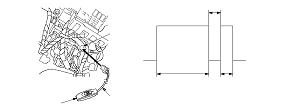
Test Mode 1
Special Tools Required

MPCS short connector
 07WAZ-0010100
  1. Turn the ignition switch to LOCK (0).
  1. Check the No. 1 (10 A) fuse in the under-dash fuse/relay box and the No. 22 (7.5 A) fuse in the under-dash fuse/relay box. If the fuse is blown, find and correct the cause, then replace the fuse.
  1. Turn the ceiling light switch in ‘‘DOOR'' (middle) position. Close all doors. Turn the ignition switch to ON (II).
    NOTE: If the driver's seat belt is unbuckled, the beeper will beep.
  1. Connect the MPCS short connector (A) to the MICU service check connector (B), and turn the switch (C) on.
  1. After 5 seconds, the ceiling light should come on for 2 seconds, go out, then blink once for 0.2 second. This means that you are in Test Mode 1 of the self-diagnostic function.
  1. About 1 second after step 5, the ceiling light will blink and indicate the DTC, and repeat it every 3 seconds. If there is more than one DTC, the system will indicate them in ascending order, beginning from the DTC with the lowest numerical value. Troubleshoot the DTCs as indicated below:
    DTC
    Cause and Troubleshooting
    1
    The MICU cannot receive signals sent from the MICU itself (for checking the sending signals), or the MICU cannot receive signals from the gauge control module. If DTC 1 only indicates, substitute a known-good gauge control module and an MICU one at a time, in that order, and recheck for the DTC after each substitution.
    5
    The MICU cannot receive signals (VSP/NE message) from the gauge control module. If DTC 5 only indicates, substitute a known-good gauge control module, and recheck for the DTC.


How to cancel the Test Mode 1
NOTE: To cancel Test Mode 1, turn off the MICU short connector switch for more than 10 seconds or turn the ignition switch to LOCK (0).
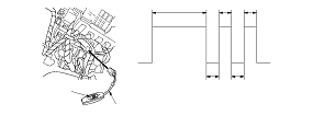
Test Mode 2
  1. While in Test Mode 1, turn off the MPCS short connector switch (A) for about 5 to 10 seconds, then turn it on again.
  1. The ceiling light should come on for 2 seconds, go out, then blinks twice more at 0.2 second intervals. This means the system has gone from Test Mode 1 to Test Mode 2.
  1. While still in Test Mode 2, operate the switches in the table shown. If the circuit is OK, the ceiling light blinks once. If the circuit is faulty, the ceiling light does not blink.
    • If the ceiling light do not blink even a switch is operated, check two or three other circuits listed in the table. If the ceiling light blinks for each circuit, the additional circuits are OK, repair the short or open circuit that failed the test in Step 3 .
    • If the ceiling light does not blink again, this multiple failed circuits mean that the control unit has failed without triggering a DTC. Test a few more circuits. If they also fail, test the MICU input test. If all the input tests prove OK, substitute a known-good MICU or gauge control module one at a time, then recheck. If the system works properly, the part that was substituted is faulty; replace it.
    Driver's door lock switch (UNLOCK)
    Driver's door lock switch (LOCK)
    Driver's door lock knob switch (UNLOCK)
    Driver's door lock knob switch (LOCK)
    Driver's door key cylinder switch (UNLOCK) *
    Driver's door key cylinder switch (LOCK) *
    Front passenger's door lock knob switch (UNLOCK) *
    Left rear door lock knob switch (UNLOCK) *
    Right rear door lock knob switch (UNLOCK) *
    Driver's door switch
    Front passengers' door switch
    Left rear door switch
    Right rear door switch
    Tailgate latch switch
    Audio switch
    Windshield wiper HI/LO switch
    Windshield wiper INT/LO switch
    Windshield wiper MIST switch
    Windshield washer switch
    Rear window wiper switch
    Rear window washer switch
    Turn signal switch (LEFT)
    Turn signal switch (RIGHT)
    Hazard warning switch
    Headlight switch (ON)
    Headlight switch (OFF)
    Lighting switch
    Dimmer switch
    Passing switch
    Hood switch *
    Brake pedal position switch
    Transmission range switch (P)
    Transmission range switch (R)
    Ignition key switch

    *:
    With security


How to cancel the Test Mode 2
NOTE: To cancel Test Mode 2, disconnect the MPCS short connector from the multiplex control inspection connector for more than 10 seconds or turn the ignition switch to LOCK (0).