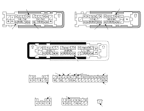
( TF09E80J32100041951FCAT00 )
Exterior Lights (MICU) Input Test

NOTE:
  • Before performing the input tests, check the No. 1, No. 5, No. 22, No. 24, No. 32, No. 34, No. 48, and No. 51 fuses in the under-dash fuse/relay box.
  • The illustration shows the RHD model and the black portion shows the lock lever. The lock lever for LHD model is shown as the dashed lines.
  1. Turn the ignition switch to LOCK (0).
  1. Disconnect under-dash fuse/relay box connectors A, B, C, K, M, N, Q, and W.
    NOTE: All connector views are wire side of female terminals.
  1. Inspect the connector and socket terminals to be sure they are all making good contact.
    • If the terminals are bent, loose or corroded, repair them as necessary and recheck the system.
    • If the terminals look OK, go to Step 5 .
  1. With the connectors still disconnected, make these input tests at the connectors.
    Cavity
    Wire
    Test condition
    Test: Desired result
    Possible cause if result is not obtained
    N2
    BLK
    Under all conditions
    Check for continuity to ground: There should be continuity.
    • Poor ground (G501)
    • An open in the wire
    K10
    BLK
    Under all conditions
    Check for continuity to ground: There should be continuity.
    • Poor ground (G502)
    • An open in the wire
    M16
    BLK
    Under all conditions
    Check for continuity to ground: There should be continuity.
    • Poor ground (G501)
    • An open in the wire
    Q9
    BLK
    Under all conditions
    Check for continuity to ground: There should be continuity.
    • Poor ground (G502)
    • An open in the wire
    W1
    YEL
    Ignition switch ON (II)
    Measure the voltage to ground: There should be battery voltage.
    • Blown No. 60 (IGN) (50 A) fuse in the under-dash fuse/relay box
    • Faulty ignition switch
    • An open in the wire
    A24
    PNK
    Ignition switch ON (II)
    Connect W1 terminal and A24 terminal with a jumper wire: The right headlight (low beam) should come on.
    • Blown bulb
    • Poor ground (G202) [G401]
    • An open in the wire
    A30
    GRN
    Ignition switch ON (II)
    Connect W1 terminal and A30 terminal with a jumper wire: The right headlight (high beam) should come on.
    • Blown bulb
    • Poor ground (G202) [G401]
    • An open in the wire
    B29
    BRN
    Ignition switch ON (II)
    Connect W1 terminal and B29 terminal with a jumper wire: The left headlight (low beam) should come on.
    • Blown bulb
    • Poor ground (G401) [G202]
    • An open in the wire
    B13
    GRY
    Ignition switch ON (II)
    Connect W1 terminal and B13 terminal with a jumper wire: The left headlight (high beam) should come on.
    • Blown bulb
    • Poor ground (G401) [G202]
    • An open in the wire
    A8
    GRY
    Ignition switch ON (II)
    Connect W1 terminal and A8 terminal with a jumper wire: The right front position light should come on.
    • Blown bulb
    • Poor ground (G202) [G401]
    • An open in the wire
    B30
    GRY
    Ignition switch ON (II)
    Connect W1 terminal and B30 terminal with a jumper wire: The left front position light should come on.
    • Blown bulb
    • Poor ground (G401) [G202]
    • An open in the wire
    C42
    GRY
    Ignition switch ON (II)
    Connect W1 terminal and C42 terminal with a jumper wire: The taillights and license plate lights should come on.
    • Blown bulb
    • Poor ground (G602, G604)
    • An open in the wire
    C21
    GRN
    Ignition switch ON (II)
    Connect W1 terminal and C21 terminal with a jumper wire: The back-up lights should come on.
    • Blown bulb
    • Poor ground (G602, G604)
    • An open in the wire

    [ ]:
    LHD model

    Cavity
    Wire
    Test condition
    Test: Desired result
    Possible cause if result is not obtained
    M8·M33
    BLU·BLK
    Combination light switch OFF
    Check for continuity between M8 and M33 terminals: There should be continuity.
    • Faulty combination light switch
    • An open in the wire
    Combination light switch in any other position than OFF
    Check for continuity between M8 and M33 terminals: There should be no continuity.
    • Faulty combination light switch
    • A short in the wire
    M7·M33
    GRY·BLK
    Combination light switch (SMALL position) ON
    Check for continuity between M7 and M33 terminals: There should be continuity.
    • Faulty combination light switch
    • An open in the wire
    Combination light switch OFF
    Check for continuity between M7 and M33 terminals: There should be no continuity.
    • Faulty combination light switch
    • A short in the wire
    M5·M33
    RED·BLK
    Combination light switch (headlight) ON
    Check for continuity between M5 and M33 terminals: There should be continuity.
    • Faulty combination light switch
    • An open in the wire
    Combination light switch OFF
    Check for continuity between M5 and M33 terminals: There should be no continuity.
    • Faulty combination light switch
    • A short in the wire
    M4·M33
    WHT·BLK
    Combination light switch lever pulled (Passing)
    Check for continuity between M4 and M33 terminals: There should be continuity.
    • Faulty combination light switch
    • An open in the wire
    Combination light switch lever released (OFF)
    Check for continuity between M4 and M33 terminals: There should be no continuity.
    • Faulty combination light switch
    • A short in the wire
    M3·M33
    LT BLU·BLK
    Combination light switch (Dimmer) in high beam position
    Check for continuity between M3 and M33 terminals: There should be continuity.
    • Faulty combination light switch
    • An open in the wire
    Combination light switch (Dimmer) in low beam position
    Check for continuity between M3 and M33 terminals: There should be no continuity.
    • Faulty combination light switch
    • A short in the wire
    B10(M/T)
    LT GRN
    Ignition switch ON (II) and shift lever in R position
    Connect W1 terminal and B10 terminal with a jumper wire: The back-up lights should come on.
    • Blown bulb
    • Faulty back-up light switch
    • Poor ground (G602, G604)
    • An open in the wire
    B26(A/T)
    GRN
    Shift lever in R position
    Check for continuity to ground: There should be continuity.
    • Faulty transmission range switch
    • Poor ground (G101)
    • An open in the wire
    Q3
    GRN [LT GRN]
    Under all condition
    Check for continuity between the Q3 terminal and the gauge control module No. 18 terminal: There should be continuity.
    An open in the wire
    Check for continuity to ground: There should be no continuity.
    A short to ground in the wire

    [ ]:
    LHD model