Clutch Replacement
|
Special Tools Required
Clutch alignment tool set
07PAF-0020000
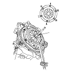
Ring gear holder
07LAB-PV00100
Sliding hammer weight
07741-0010201
Driver handle, 15 x 135 L
07749-0010000
Bearing remover shaft 15
07936-KC10100
Bearing remover head 15
07936-KC10200
Bearing driver attachment, 28 x 30 mm
07946-1870100
Engine Side
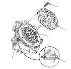
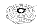
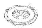
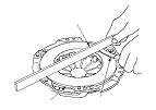
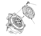
Pressure Plate Inspection and Removal
|
|
|
|
|
|
|
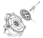
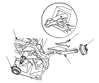
Clutch Disc Inspection and Removal
|
|
|
|
|
|
|
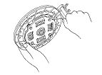
Flywheel Inspection
|
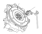
|
|
Flywheel Replacement
|
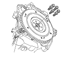
|
|
|
|
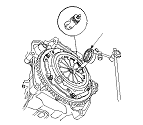
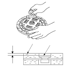
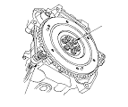
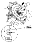
Pilot Bearing Inspection
|
|
|
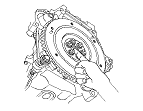
Pilot Bearing Replacement
|
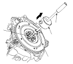
|
|
|
|
Clutch Disc and Pressure Plate Installation
|
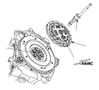
|
|
|
|
|
|
Transmission Side
Release Bearing Removal
|
|
|
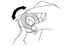
Release Bearing Inspection
|
|
|
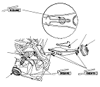
Release Bearing Installation
|
|
|
|