Clutch Replacement
|
Special Tools Required
Stop collar
070AF-SMGC150
Ring gear holder
07LAB-PV00100
Pressure plate compressor
070AE-0010100
Center shaft
070AF-SMGC140
Bearing remover shaft 15
07936-KC10100
Bearing remover head 15
07936-KC10200
Driver handle, 15 x 135L
07749-0010000
Bearing driver attachment, 28 x 30 mm
07946-1870100
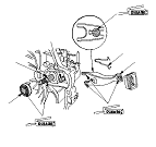
Engine Side

You must use the pressure plate compressor, the center shaft, and the stop collar required to remove and install the clutch pressure plate or you will damage it.
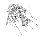
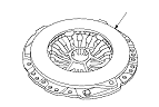
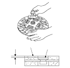
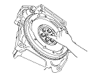
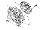
Pressure Plate Inspection and Removal
|
|
|
|
|
|
|
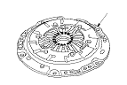
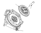
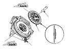
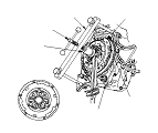
Clutch Disc Inspection and Removal
|
|
|
|
|
|
|
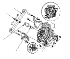
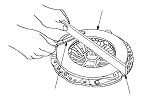
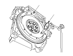
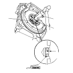
Flywheel Inspection
|
|
|
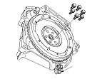
Flywheel Replacement
|
|
|
|
|
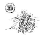
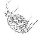
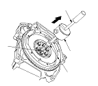
Pilot Bearing Inspection
|
|
|
Pilot Bearing Replacement
|
|
|
|
|
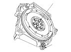
Clutch Disc and Pressure Plate Installation
NOTE: The clutch disc and pressure plate are a matched set and must be replaced together.
|
|
|
|
|
|
|
Transmission Side
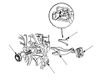
Release Bearing Removal
|
|
|
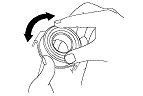
Release Bearing Inspection
|
|
|
Release Bearing Installation
|
|
|
|
|
|