( TF09E1PK77100000000BBAT20 )
How to Troubleshoot the A/T System

How to Check for DTCs with the Honda Diagnostic System (HDS)
When the powertrain control module (PCM) senses an abnormality in the input or output system, the D indicator (A) in the gauge assembly (B) will usually blink.

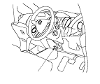
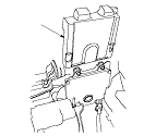
When the Honda Diagnostic System (HDS) is connected to the data link connector (DLC) (A) (located under the driver's dashboard lower cover), it will indicate the diagnostic trouble code (DTC) when the ignition switch is turned to ON (II) and the appropriate menu is selected.
If the D indicator or malfunction indicator lamp (MIL) has been reported on, or if a driveability problem is suspected, follow this procedure:
  1. Connect the HDS to the DLC. (See the HDS user's manual for specific instructions.)
  1. Turn the ignition switch to ON (II), select A/T system, and observe the DTC in the DTCs MENU on the HDS screen. If the HDS does not communicate with the PCM, go to the DLC circuit troubleshooting.
  1. Record the freeze data and the on-board snapshots for all fuel and emissions DTCs and A/T DTCs.
  1. If there is a fuel and emissions DTC, first check the fuel and emissions system as indicated by the DTC.
  1. Clear the DTC and data.
  1. Drive the vehicle for several minutes under the same conditions as those indicated by the freeze data, and then recheck for a DTC. If the A/T DTC returns, go to the indicated DTC's troubleshooting. If the DTC does not return, there was an intermittent problem within the circuit. Make sure all pins and terminals in the circuit are tight.

Symptom Troubleshooting Versus DTC Troubleshooting
Some symptoms will not trigger DTCs or cause the D indicator to blink. If the malfunction indicator lamp (MIL) was reported ON or the D indicator has been blinking, check for DTCs. If the vehicle has an abnormal symptom, and there are no DTCs stored, do the symptom troubleshooting. Check the list of probable cause(s) for the symptom, in the sequence listed, until you find the problem.

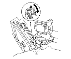
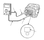
How to Troubleshoot Circuits at the PCM Connectors
NOTE: Monitoring the powertrain control system throughout the vehicle, the PCM stays on up to 60 minutes after the ignition switch is turned to LOCK (0). Jumping the SCS line after turning the ignition switch to LOCK (0) cancels this function. Disconnecting the PCM during this function, without jumping the SCS line first, can damage the PCM.
  1. Connect the HDS to the DLC (A), and jump the SCS line with the HDS.
    NOTE: If the HDS does not communicate with the PCM, troubleshoot the DLC circuit.

  1. Disconnect PCM connectors A, B, and C.

  1. Connect one side of the patch cord (A) terminal to a digital multimeter (B), and connect the other side of the patch cord terminals to a commercially available banana jack (Pomona Electronics Tool No. 3563 or equivalent) (C).
  1. Gently slide the pin probe into the inspection port (D) at the connector terminal side. Always use the inspection port. Do not slide the probe into the connector terminals.
    • For accurate result, always use the pin probe (male).
    • To prevent damage to the connector terminals, do not insert test equipment probes, paper clips, or other substitutes as they can damage the terminals. Damaged terminals cause a poor connection and an incorrect measurement.
    • Do not puncture the insulation on a wire. Punctures can cause poor or intermittent electrical connections.

How to Clear A/T DTCs
  1. Connect the HDS to the DLC (A).
  1. Turn the ignition switch to ON (II).
  1. Clear the DTC(s) with the HDS.
    NOTE: If the HDS does not communicate with the PCM, troubleshoot the DLC circuit.

OBD Status
The OBD status shows the current system status of each DTC and all of the parameters. This function is used to see if the technician's repair was successfully finished. The results of diagnostic tests for the DTC are displayed as:
  • PASSED: On board diagnosis is successfully finished.
  • FAILED: On board diagnosis has finished but failed.
  • NOT COMPLETED: The on board diagnosis was running but is out of the enable conditions of the DTC.

How to End a Troubleshooting Session (required after any troubleshooting)
  1. Reset the PCM with the HDS while the engine is stopped.
  1. Turn the ignition switch to LOCK (0).
  1. Turn the ignition switch to ON (II), and wait for 30 seconds.
  1. Turn the ignition switch to LOCK (0), and disconnect the HDS from the DLC.
  1. Start the engine in P or N, and warm it up to normal operating temperature (the radiator fan comes on).
  1. To verify that the problem is repaired, test-drive the vehicle for several minutes at speeds over 50 km/h (30 mph) or under the same conditions as those indicated by the freeze data.

Updating the A/T software in the PCM
Refer to the PCM Update when the A/T software updating is needed in the DTC troubleshooting.

Replacing the PCM
Refer to the PCM Replacement when replacing the PCM is needed in the DTC troubleshooting.

How to Substitute the PCM
  1. Turn the ignition switch to LOCK (0).
  1. Connect the HDS to the DLC (A).
  1. Turn the ignition switch to ON (II), and make sure the HDS communicates with the PCM. If it doesn't, go to the DLC circuit troubleshooting.
  1. Turn the ignition switch to LOCK (0).

  1. Remove the PCM cover (A).

  1. Remove the mounting bolts (A) from the PCM (B).
  1. Disconnect PCM connectors A (C), B (D), and C (E), and remove the PCM.
  1. Install a known-good PCM in the reverse order of removal.
  1. Open the SCS line with the HDS.
  1. Turn the ignition switch to ON (II).
    NOTE: If DTC P0630 ‘‘VIN not Programmed or Mismatch'' will be stored because the VIN has not been programmed into the PCM; ignore it, and continue this procedure.
  1. Manually input the VIN to the PCM with the HDS.
  1. Select the IMMOBI SYSTEM with the HDS.
  1. Enter the immobilizer code using the PCM replacement procedure in the HDS; this allows you to start the engine.
  1. Reset the PCM with the HDS.
  1. Update the PCM if it does not have the latest software.