( TF09E1PE10480139301KCAT00 )
A/T Valve Body and ATF Strainer Installation

  1. Make sure that the ATF magnet is cleaned and installed in the torque converter housing.
    Torque Specifications;
    6 x 1.0 mm:
    12 N·m (1.2 kgf·m, 8.7 lbf·ft)
    8 x 1.25 mm:
    18 N·m (1.8 kgf·m, 13 lbf·ft)

  1. Install the main separator plate and two dowel pins on the torque converter housing.

  1. Install the ATF pump drive gear (A), ATF pump driven gear (B), and ATF pump driven gear shaft (C). Install the ATF pump driven gear with its grooved and chamfered side facing down.
  1. Install the main valve body.

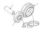
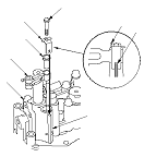
  1. Make sure the ATF pump drive gear (A) rotates smoothly in the normal operating direction, and the ATF pump driven gear shaft (B) moves smoothly in the axial and normal operating direction.
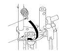
  1. If the ATF pump drive gear and ATF pump driven gear shaft do not move smoothly, loosen the main valve body bolts. Realign the ATF pump driven gear shaft, and retighten the bolts to the specified torque, then recheck. Failure to align the ATF pump driven gear shaft correctly will result in a seized ATF pump drive gear or ATF pump driven gear shaft.
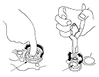
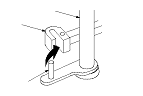
  1. Make sure that the three check balls and the cooler check valve are in the main valve body, then install the cooler check valve spring in the cooler check valve.
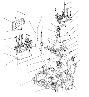
  1. Install the ATF joint pipes between the main valve body and the torque converter housing.
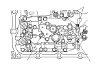
  1. Install the regulator separator plate and two dowel pins on the main valve body.
  1. Install the new O-ring on the stator shaft, and install the stator shaft and stator shaft stop.
  1. Install the regulator valve body (10 bolts).
  1. Install the servo separator plate and two dowel pins on the main valve body.

  1. Install the servo body (11 bolts). Install the ATF strainer with the two bolts in the bolt holes (A) in step 17, and install the baffle plate with the two bolts in the bolt holes (B) in step 4 in shaft assembly and housing installation.

  1. If the detent arm was removed, install the detent arm (A) with arm collar (B) on the servo body (C), and install the new lock washer (D) by aligning its cutout (E) with the projection (F) of the servo body. Install and tighten the bolt, then bend the lock tab (G) of the lock washer against the bolt head.

  1. Install the control shaft (A) in the torque converter housing while aligning the manual valve lever pin (B) on the control shaft with the guide of the manual valve (C).

  1. Hook the detent arm spring (A) to the detent arm (B).
  1. Install the new O-ring on the ATF strainer, and install the ATF strainer (two bolts).
  1. Install the 8 x 180.5 mm ATF feed pipe in the regulator valve body.
  1. Install the 8 x 192.5 mm ATF feed pipe and 8 x 180.5 mm ATF feed pipe in the servo body.