( TF09E00K801000R2711FAAT00 )
VSA DTC Troubleshooting: 27-11, 27-26

DTC 27-11:
 Steering Angle Sensor DIAG Signal Error (Initial)
DTC 27-26:
 Steering Angle Sensor DIAG Signal Error (Main)
  1. Turn the ignition switch to ON (II).
  1. Clear the DTC with the HDS.
  1. Turn the ignition switch to LOCK (0), then turn it to ON (II) again.
  1. Check for DTCs with the HDS.
Is DTC 27-11 or 27-26 indicated?
YES -
Go to Step 5 .
NO -
Intermittent failure, the system is OK at this time. Check for loose terminals between the steering angle sensor 5P connector and the VSA modulator-control unit 36P connector. Refer to intermittent failures troubleshooting.
  1. Turn the ignition switch to LOCK (0).
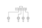
  1. Check for continuity between body ground and steering angle sensor 5P connector terminals No. 2, No. 3, No. 4, and No. 5 individually.
Is there continuity?
YES -
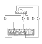
Repair short to body ground in the wire between the steering angle sensor and the VSA modulator-control unit.■
NO -
Go to Step 9 .

  1. Check for continuity between the VSA modulator-control unit 36P connector terminal and the steering angle sensor 5P connector terminal individually.
    Sign
    VSA Modulator-control Unit 36P Connector Terminal
    Steering Angle Sensor 5P Connector Terminal
    SVCC
    No. 9
    No. 5
    STR-A
    No. 11
    No. 2
    STR-D
    No. 26
    No. 3
    STR-B
    No. 27
    No. 4
    SGND
    No. 34
    No. 1

Is there continuity?
YES -
Go to Step 10 .
NO -
Repair open in the wire between the steering angle sensor and the VSA modulator-control unit.■
  1. Reconnect all connectors.
  1. Turn the ignition switch to ON (II).
  1. Clear the DTC with the HDS.
  1. Turn the ignition switch to LOCK (0), then turn it to ON (II) again.
  1. Check for DTCs with the HDS.
Is DTC 27-11 or 27-26 indicated?
YES -
Go to Step 16 .
NO -
  1. Turn the ignition switch to LOCK (0), then turn it to ON (II) again.
  1. Check for DTCs with the HDS.
Is DTC 27-11 or 27-26 indicated?
YES -
Check for loose terminals in the VSA modulator-control unit 36P connector. If the VSA modulator-control unit was updated, substitute a known-good VSA modulator-control unit, then retest. If the VSA modulator-control unit was substituted, go to Step 1 .
NO -
If the VSA modulator-control unit was updated, troubleshooting is complete. If the VSA modulator-control unit was substituted, replace the original VSA modulator-control unit. If any other DTCs are indicated, go to the indicated DTCs troubleshooting.■