( TF09E00K80100000000BBAT00 )
How to Troubleshoot the VSA System
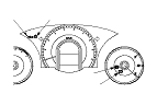
System Indicator
This system has four indicators:
  • ABS indicator (A)
  • Brake system indicator (B)
  • VSA indicator (C)
  • VSA activation indicator (D)
When the system is OK, each indicator comes on for about 2 seconds after turning the ignition switch to ON (II), then goes off.
When the system detects a problem, a DTC will be set and, depending upon the failure, the VSA modulator-control unit will determine which indicator(s) will be turned on. If the problem goes away (system returns to normal), the indicator(s) will be controlled in the following way depending upon the DTC that was set:
  • The indicator(s) will come on and stay on when the ignition switch is ON (II).
  • The indicator(s) will automatically go off.
  • The indicator(s) will go off after the vehicle is driven.

ABS Indicator

The ABS indicator comes on when the ABS function is lost. The brakes still work like a conventional system.

Brake System Indicator

The brake system indicator comes on when the EBD function is lost, the parking brake is applied, and/or the brake fluid level is low.
NOTE: If two or more wheel speed sensors fail, the brake system indicator will come on.

VSA Indicator

The VSA indicator comes on when the VSA function is lost.

VSA Activation Indicator

The VSA activation indicator blinks when the VSA function is activating. The VSA activation indicator comes on, when the VSA is turned OFF by using the VSA OFF switch, or the VSA function is lost.

Diagnostic Trouble Code (DTC)
  • The memory can hold all DTCs. However, when the same DTC is detected more than once, the more recent DTC is written over the earlier one. Therefore, when the same problem is detected repeatedly, it is memorized as a single DTC.
  • The DTCs are indicated in ascending number order, not in the order they occur.
  • The DTCs are memorized in the EEPROM. Therefore, the memorized DTCs cannot be erased by disconnecting the battery. Do the specified procedures to clear the DTCs.

Self-diagnosis
  • Self-diagnosis can be classified into two categories:
  • -
    Initial diagnosis: Done right after the ignition switch is turned to ON (II) and until the ABS and VSA indicators go off.
    -
    Regular diagnosis: Done right after the initial diagnosis until the ignition switch is turned to LOCK (0).
  • When the system detects a problem, the VSA modulator-control unit shifts to fail-safe mode.

Kickback
The pump motor operates when the VSA modulator-control unit is functioning, and the fluid in the reservoir is forced out to the master cylinder, causing kickback at the brake pedal.
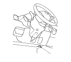
Pump Motor
  • The pump motor operates when the VSA modulator-control unit is functioning.
  • The VSA modulator-control unit checks the pump motor operation one time after completing initial diagnosis during regular diagnosis when the vehicle is driven over 15 km/h (10 mph).

Brake Fluid Replacement/Air Bleeding
Brake fluid replacement and air bleeding procedures are identical to the procedures used on vehicles without the VSA system.

How to Troubleshoot DTCs
The troubleshooting procedures assume that the cause of the problem is still present and the ABS and/or VSA indicator is still on. Following a troubleshooting procedure for a code that has been cleared but does not reset can result in incorrect diagnosis.
  1. Question the customer about the conditions when the problem occurred, and try to reproduce the same conditions for troubleshooting. Find out when the ABS and/or VSA indicator came on, such as during activation, after activation, when the vehicle was traveling at a certain speed, etc. If necessary, have the customer demonstrate the concern.
  1. When the ABS or VSA indicator does not come on during the test-drive, but troubleshooting is done based on the DTC, check for loose connectors, poor contact of the terminals, etc. before you start troubleshooting.
  1. After troubleshooting, or the repairs are done, clear the DTCs, and test-drive the vehicle under the same conditions that originally set the DTCs. Make sure the ABS and VSA indicators do not come on.
  1. Check for DTCs from other systems which are connected via F-CAN. If there are DTCs that are related to F-CAN, the most likely cause was that the ignition switch was turned to ON (II) with the VSA modulator-control unit connector disconnected. Clear the DTCs. Check for fuel and emissions, and VSA codes, first. Be sure to troubleshoot those first.

Intermittent Failures
The term ‘‘intermittent failure'' means a system may have had a failure, but it checks OK now. If the indicator(s) of the system does not come on, check for loose connectors or poor contacts in the terminals related to the circuit that you are troubleshooting.

How to Use the HDS (Honda Diagnostic System)
  1. If the system indicators stay on, connect the HDS to the data link connector (DLC) (A) located under the driver's side of the dashboard.
  1. Turn the ignition switch to ON (II).
  1. Make sure the HDS communicates with the vehicle and the VSA modulator-control unit. If it doesn't, troubleshoot the DLC circuit.
  1. Check the diagnostic trouble code (DTC) and note it. Then refer to the indicated DTC's troubleshooting, and do the appropriate troubleshooting procedure.
    NOTE:
    • The HDS communication will be stopped when the vehicle speed is at 50 km/h (31 mph) or more.
    • The HDS can read the DTC, the current data, and other system data.
    • For specific operations, refer to the Help menu that came with the HDS.

How to Retrieve DTCs
  1. With the ignition switch in LOCK (0), connect the HDS to the data link connector (DLC) under the driver's side of the dashboard.
  1. Turn the ignition switch to ON (II).
  1. Make sure the HDS communicates with the vehicle and the VSA modulator-control unit. If it doesn't troubleshoot the DLC circuit.
  1. Follow the prompts on the HDS to display the DTC(s) on the screen. After determining the DTC, refer to the DTC troubleshooting.
  1. Turn the ignition switch to LOCK (0).

How to Clear DTCs
  1. With the ignition switch in LOCK (0), connect the HDS to the data link connector (DLC) under the driver's side of the dashboard.
  1. Turn the ignition switch to ON (II).
  1. Make sure the HDS communicates with the vehicle and the VSA modulator-control unit. If it doesn't troubleshoot the DLC circuit.
  1. Clear the DTC(s) by following the screen prompts on the HDS.
  1. Turn the ignition switch to LOCK (0).