|
DTC 51-01:
Torque Sensor (VT1 and VT2) (Regular Diagnosis)
DTC 51-02:
Torque Sensor VT3 Differential-amplification Function (Regular Diagnosis)
DTC 51-03:
Torque Sensor (VT1, VT2 Rapid-change) (Regular Diagnosis)
DTC 51-04:
Torque Sensor (Temperature) (Regular Diagnosis)
DTC 51-05:
Torque Sensor (Coil) (Regular Diagnosis)
-
Turn the ignition switch to ON (II).
-
Clear the DTC with the HDS.
-
Turn the ignition switch to LOCK (0).
-
Start the engine.
-
Turn the steering wheel from lock to lock several times, and hold the steering wheel for 10 seconds or more.
-
Check for DTCs with the HDS.
|
Is DTC 51-01, 51-02, 51-03, 51-04, or 51-05 indicated?
|
|
YES
|
-
|
|
|
NO
|
-
|
Intermittent failure, the system is OK at this time. Check for poor connections or loose terminals at the EPS motor and the EPS control unit.■
|
-
Turn the ignition switch to LOCK (0).
-
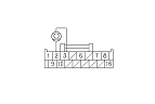
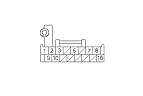
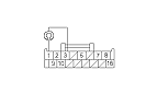
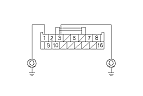
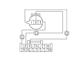
Disconnect the EPS control unit connector C (16P).
-
Measure the resistance between EPS control unit connector C (16P) terminals No. 2 and No. 3.
|
Is there resistance 10 Ω or less at 20 °C (68 °F)?
|
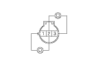
-
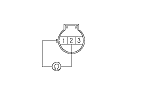
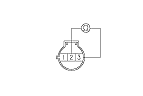
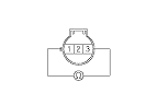
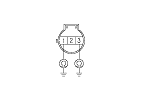
Disconnect the torque sensor 3P connector.
|