|
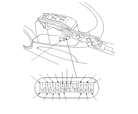
NOTE: The power window control unit is built into the power window master switch.
-
-
Disconnect the 22P connector (A) from the power window master switch.
-
Inspect the connector and socket terminals to be sure they are all making good contact.
-
With the connector still disconnected, make these input tests at the connector.
NOTE: Before testing, make sure the No. 1 (10 A), No. 22 (7.5 A), and No. 60 (50 A) fuse in the under-dash fuse/relay.
|
Cavity
|
Wire
|
Test condition
|
Test: Desired result
|
Possible cause if desired result is not obtained
|
|
3 [4]
|
GRY
|
Under all conditions
|
Measure the voltage to ground: There should be battery voltage.
|
|
|
4 [3]
|
BRN
|
Ignition switch ON (II)
|
Measure the voltage to ground: There should be battery voltage.
|
-
Blown No. 17 (20 A) fuse in the under-dash fuse/relay box
-
Faulty under-dash fuse/relay box
-
Faulty power window relay (P/W)
-
Faulty MICU
-
An open in the wire
|
|
15
|
PUR
|
Ignition switch ON (II)
|
Measure the voltage to ground: There should be battery voltage.
|
-
Blown No. 18 (20 A) fuse in the under-dash fuse/relay box
-
Faulty under-dash fuse/relay box
-
Faulty power window relay (P/W)
-
Faulty MICU
-
An open in the wire
|
|
20
|
RED
|
Ignition switch ON (II)
|
Measure the voltage to ground: There should be battery voltage.
|
-
Blown No. 19 (20 A) fuse in the under-dash fuse/relay box
-
Faulty under-dash fuse/relay box
-
Faulty power window relay (P/W)
-
Faulty MICU
-
An open in the wire
|
|
11
|
BLK
|
Under all conditions
|
Check for continuity to ground: There should be continuity.
|
-
Poor ground (G501)
-
An open in the wire
|
|
12
|
BLK
|
Under all conditions
|
Check for continuity to ground: There should be continuity.
|
-
Poor ground (G501)
-
An open in the wire
|
|
9 [2]
|
YEL
|
Ignition switch ON (II)
|
Connect the No. 4 [No. 3] and the No. 9 [No. 2] terminals, and No. 10 [No. 1] and No. 11 terminals momentarily with jumper wires: The front passenger's window should go down.
|
-
Blown No. 17 (20 A) fuse in the under-dash fuse/relay box
-
Faulty under-dash fuse/relay box
-
Faulty front passenger's power window motor
-
Faulty front passenger's power window switch
-
Poor ground (G501)
-
An open in the wire
|
|
10 [1]
|
WHT
|
Ignition switch ON (II)
|
Connect the No. 4 [No. 3] and the No. 10 [No. 1] terminals, and No. 9 [No. 2] and No. 11 terminals momentarily with jumper wires: The front passenger's window should go up.
|
|
13
|
LT GRN
|
Ignition switch ON (II)
|
Connect the No. 15 and the No. 13 terminals, and No. 14 and No. 11 terminals momentarily with jumper wires: The right rear window should go up.
|
-
Blown No. 18 (20 A) fuse in the under-dash fuse/relay box
-
Faulty under-dash fuse/relay box
-
Faulty right rear power window motor
-
Faulty right rear power window switch
-
Poor ground (G501)
-
An open in the wire
|
|
14
|
RED
|
Ignition switch ON (II)
|
Connect the No. 15 and the No. 14 terminals, and No. 13 and No. 11 terminals momentarily with jumper wires: The right rear window should go down.
|
|
Cavity
|
Wire
|
Test condition
|
Test: Desired result
|
Possible cause if desired result is not obtained
|
|
21
|
GRN
|
Ignition switch ON (II)
|
Connect the No. 20 and the No. 21 terminals, and No. 22 and No. 11 terminals momentarily with jumper wires: The left rear window should go down.
|
-
Blown No. 19 (20 A) fuse in the under-dash fuse/relay box
-
Faulty under-dash fuse/relay box
-
Faulty left rear power window motor
-
Faulty left rear power window switch
-
Poor ground (G501)
-
An open in the wire
|
|
22
|
PUR
|
Ignition switch ON (II)
|
Connect the No. 20 and the No. 22 terminals, and No. 21 and No. 11 terminals momentarily with jumper wires: The left rear window should go up.
|
|
1 [10]
|
ORN
|
Connect the No. 3 [No. 4] and the No. 1 [No. 10] terminals, and No. 2 [No. 9] and No. 12 terminals momentarily with jumper wires
|
Check driver's power window motor operation: The driver's window should go up.
|
-
Blown No. 3 (20 A) fuse in the under-dash fuse/relay box
-
Faulty under-dash fuse/relay box
-
Faulty driver's power window motor
-
Poor ground (G501)
-
An open in the wire
|
|
2 [9]
|
BLU
|
Connect the No. 3 [No. 4] and the No. 2 [No. 9] terminals, and No. 1 [No. 10] and No. 12 terminals momentarily with jumper wires
|
Check driver's power window motor operation: The driver's window should go down.
|
-
Reconnect the 22P connector to the power window master switch. Turn the ignition switch to ON (II), and make these input tests at the connector.
|
Cavity
|
Wire
|
Test condition
|
Test: Desired result
|
Possible cause if desired result is not obtained
|
|
7
|
LT GRN
|
Ignition switch ON (II)
|
Check for continuity to ground: There should be continuity.
|
|
|
16
|
WHT
|
Ignition switch ON (II)
|
Measure the voltage to ground: There should be battery voltage.
|
|
|
5
|
GRN
|
Ignition switch ON (II), and driver's window switch moving up or down
|
Measure the voltage between the No. 5 and No. 7 terminals: There should be 0 V−about 5 V−0 V− about 5 V repeatedly (a digital voltmeter should reads about 2.5 V while the window moves).
|
-
Faulty power window master switch
-
Faulty driver's power window motor
-
An open in the wire
-
A short to ground in the wire
|
|
6
|
PNK
|
Ignition switch ON (II), and driver's power window switch moving up or down
|
Measure the voltage between the No. 6 and No. 7 terminals: There should be 0 V−about 5 V−0 V− about 5 V repeatedly (a digital voltmeter should reads about 2.5 V while the window moves).
|
|
|