( TF09E00J26370141951FCAT00 )
Safety Indicator System (MICU and Gauge Control Module) Input Test

NOTE: Before testing, do the gauge control module self-diagnostic function to make sure the door indicator LED and B-CAN communication line are OK.
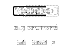
MICU
  1. Turn the ignition switch to LOCK (0).
  1. Disconnect under-dash fuse/relay box connectors C, K, M, N, Q, and W.
    NOTE:
    • All connector views are shown from wire side of female terminals.
    • The illustration shows the RHD model and the black portion shows the lock lever. The lock lever for LHD model is shown as the dashed lines.
  1. Inspect the connector and socket terminals to be sure they are all making good contact.
    • If the terminals are bent, loose, or corroded, repair them as necessary and recheck the system.
    • If the terminals look OK, go to Step 5 .
  1. With the connectors still disconnected, make these input tests at the connectors.
    • If any test indicates a problem, find and correct the cause, then recheck the system.
    • If all the input tests prove OK, go to Step 6 .
    Cavity
    Wire
    Test condition
    Test: Desired result
    Possible cause if desired result is not obtained
    K10
    BLK
    Under all conditions
    Check for continuity to ground: There should be continuity.
    • Poor ground (G502)
    • An open in the wire
    M16
    BLK
    Under all conditions
    Check for continuity to ground: There should be continuity.
    • Poor ground (G501)
    • An open in the wire
    N2
    BLK
    Under all conditions
    Check for continuity to ground: There should be continuity.
    • Poor ground (G501)
    • An open in the wire
    Q9
    BLK
    Under all conditions
    Check for continuity to ground: There should be continuity.
    • Poor ground (G502)
    • An open in the wire
    W1
    YEL
    Ignition switch ON (II)
    Measure the voltage to ground: There should be battery voltage.
    • Blown No. 60 (50 A) fuse in the under-dash fuse/relay box
    • Faulty ignition switch
    • An open in the wire
    Q3
    GRN[LT GRN]
    Disconnect the gauge control module 32P connector
    Check for continuity between Q3 terminal and the gauge control module 32P connector No. 18 terminal: There should be continuity.
    An open in the wire
    Check for continuity to ground: There should be no continuity.
    A short to ground in the wire
    C33
    BLU
    Driver's door open
    Check for continuity to ground: There should be continuity.
    • Faulty driver's door switch
    • An open in the wire
    Driver's door closed
    Check for continuity to ground: There should be no continuity.
    • Faulty driver's door switch
    • A short to ground in the wire
    C32
    LT GRN
    Front passenger's door open
    Check for continuity to ground: There should be continuity.
    • Faulty front passenger's door switch
    • An open in the wire
    Front passenger's door closed
    Check for continuity to ground: There should be no continuity.
    • Faulty front passenger's door switch
    • A short to ground in the wire
    C32 *2
    LT GRN
    Left rear door or right rear door open
    Check for continuity to ground: There should be continuity.
    • Faulty left rear door switch
    • Faulty right rear door switch
    • An open in the wire
    Left rear door and right rear door closed
    Check for continuity to ground: There should be no continuity.
    • Faulty left rear door switch
    • Faulty right rear door switch
    • A short to ground in the wire
    C40 *1
    GRN
    Left rear door open
    Check for continuity to ground: There should be continuity.
    • Faulty left rear door switch
    • An open in the wire
    Left rear door closed
    Check for continuity to ground: There should be no continuity.
    • Faulty left rear door switch
    • A short to ground in the wire
    C26 *1
    PNK
    Right rear door open
    Check for continuity to ground: There should be continuity.
    • Faulty right rear door switch
    • An open in the wire
    Right rear door closed
    Check for continuity to ground: There should be no continuity.
    • Faulty right rear door switch
    • A short to ground in the wire
    C22
    ORN
    Tailgate open
    Check for continuity to ground: There should be continuity.
    • Faulty tailgate latch switch
    • An open in the wire
    Tailgate closed
    Check for continuity to ground: There should be no continuity.
    • Faulty tailgate latch switch
    • A short to ground in the wire

    *1:
    With security
    *2:
    Without security


Gauge
  1. Turn the ignition switch to LOCK (0), and remove the instrument panel.
  1. Inspect the connector and socket terminals to be sure they are all making good contact.
    • If the terminals are bent, loose, or corroded, repair them as necessary and recheck the system.
    • If the terminals look OK, go to Step 9 .
  1. With the connectors still disconnected, make these input tests at the connectors.
    • If any test indicates a problem, find and correct the cause, then recheck the system.
    • If al the input tests prove OK, go to Step 10 .
    Cavity
    Wire
    Test condition
    Test: Desired result
    Possible cause if desired result is not obtained
    13
    BLK
    Under all conditions
    Check for continuity to ground: There should be continuity.
    • Poor ground (G501)
    • An open in the wire
    17
    BLK
    Under all conditions
    Check for continuity to ground: There should be continuity.
    • Poor ground (G501)
    • An open in the wire
    16
    PNK
    Under all conditions
    Measure the voltage to ground: There should be battery voltage.
    • Blown No. 1 (10 A) fuse in the under-dash fuse/relay box
    • An open in the wire
    32
    LT BLU
    Ignition switch ON (II)
    Measure the voltage to ground: There should be battery voltage.
    • Blown No. 22 (7.5 A) fuse in the under-dash fuse/relay box
    • Faulty under-dash fuse/relay box
    • An open in the wire

  1. Substitute a known-good gauge control module, and recheck the system.