( TF09E00D52100063635KDAT00 )
VSA Modulator-control Unit Removal and Installation

NOTE:
  • Do not spill brake fluid on the vehicle; it may damage the paint; if brake fluid gets on the paint, wash it off immediately with water.
  • Be careful not to damage or deform the brake lines during removal and installation.
  • Plug the end of a hose and joints to prevent spilling brake fluid.
Removal
  1. Turn the ignition switch to LOCK (0).
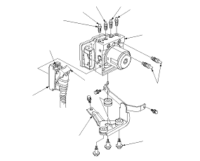
  1. Disconnect the VSA modulator-control unit 36P connector (A) by pushing the lock (B) and pulling down the lever (C); the connector disconnects itself.
  1. Disconnect the six brake lines from the VSA modulator-control unit.
    NOTE: Brake lines are connected to the master cylinder (D) and to the left-front (E), the right-front (F), the left-rear (G), and the right-rear (H) brake systems.
  1. Remove the VSA modulator-control unit (I) with the bracket (J) from the body.
  1. Remove the VSA modulator-control unit from the bracket.

Installation
  1. Install the VSA modulator-control unit onto the bracket.
  1. Install the bracket with the VSA modulator-control unit to the body.
  1. Reconnect the six brake lines, then tighten the flare nuts to the specified torque.
  1. Align the connecting surface of the VSA modulator-control unit 36P connector to the VSA modulator-control unit.
  1. Pull up the lever of the VSA modulator-control unit 36P connector, then confirm the connector is fully seated.
  1. Start the engine, and check that the ABS and the VSA indicators go off.
  1. Test-drive the vehicle, and make sure that the ABS and the VSA indicators do not come on.
    NOTE: If the brake pedal is spongy, there may be air trapped in the modulator which could then be induced into the normal brake system during modulation. Bleed the brake system again.