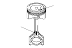
Piston, Pin, and Connecting Rod Replacement
-
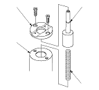
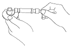
Temporarily install the pilot collar over the piston pin base insert (A), and adjust the piston base head inserts as shown, then tighten the screws (B). Remove the pilot collar.
|
|
-
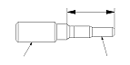
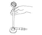
Assemble and adjust the length of the piston pin driver head and shaft to 57 mm (2.2 in.).
|
|
-
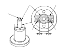
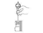
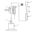
With the arrow on top of the piston pointing up, place the piston assembly (A) on the special tool (B).
Be sure you position the recessed flat area of the piston against the piston base head inserts (C) as shown.
-
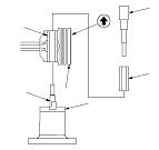
Press the pin (D) out with the pin driver (E), the pilot collar (F), and a hydraulic press.
|
|
|
Inspection
-
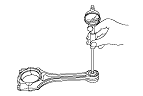
Measure the diameter of the piston pin.
Piston Pin Diameter
|
Standard (New):
|
17.996−18.000 mm (0.7085−0.7087 in.)
|
|
|
-
Zero the dial indicator to the piston pin diameter.
|
|
-
Measure the piston pin-to-piston clearance.
Piston Pin-to-Piston Clearance
|
Standard (New):
|
0.010−0.017 mm (0.0004−0.0007 in.)
|
|
|
-
Check the difference between the piston pin diameter and connecting rod small end diameter.
Piston Pin-to-Connecting Rod Interference
|
Standard (New):
|
0.019−0.036 mm (0.0007−0.0014 in.)
|
|
|
|
Reassembly
-
Assemble the piston and connecting rod with the arrow (A) and the embossed mark (B) on the same side.
|
|
-
Insert the pilot collar (A) into the piston and the connecting rod.
-
With the arrow on top of the piston and the embossed mark on the connecting rod facing up, place the piston assembly (B) on the special tool (C). Be sure you position the recessed flat area of the piston against the piston base head inserts (D) as shown.
-
Press the pin (E) in with the pin driver (F) and a hydraulic press.
|
|