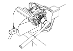
Alternator Overhaul
|
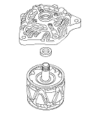
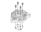
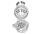
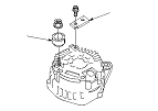
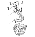
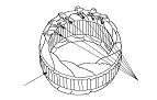
Exploded View
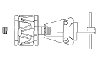
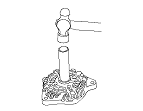
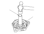
Special Tools Required
Driver handle, 15 x 135L
07749-0010000
Bearing driver attachment, 42 x 47 mm
07746-0010300
NOTE: Refer to the Exploded View as needed during this procedure.
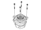
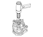
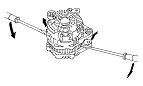
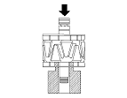
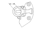
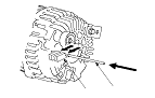
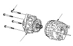
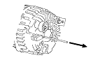
Alternator Disassembly
|
|
|
|
|
|
|
|
|
|
|
|
|
|
|
|
|
|
|
|
|
|
|
|
|
|
|
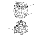
Stator side
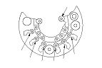
Rear housing side
|
|
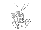
Alternator Brush Inspection
|
|
||||||
|
|
|
Rotor Slip Ring Test
|
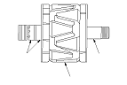
|
|
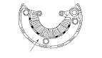
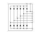
Stator Test
|
|
|
|
|
|